ITXPlus: A ITX Sized Macintosh Plus Logicboard Reproduction

max1zzz

Moderator
Staff member
Sep 23, 2021
253
628
93
28
I haven't done project thread in a while as writing is not my favourite past time but people seem to enjoy them so here it goes

ITXPlus is a Mini-ITX sized Macintosh Plus logicboard clone that can be be assembled to a working state with no original parts and is intended for new build systems in modern cases

ITXPlus features a onboard VGA output using GuruThree's Pico based video converter, power from standard 24pin ATX power supply, a onboard 50pin internal scsi header and 4MB of soldered RAM

ITXPlus also makes used of DosFox's discreet replacement for the Sony Sound IC and my implementation of his SCHWIM IWM bypass in a PLD as well as pgreenland / quortan's ATTiny based RTC replacement and Porchy / Hkz / Bolle's reverse engineerings of the Macintosh Plus PAL's

(I hope I haven't forgotten to mention anyone's elses work I have used....)

As it is designed to use a SCHWIM based IWM bypass it will not support floppy drives out of the box however a expansion heder is provided with all the signals required to connect a real IWM should you want to do this

With execption of the 68000, connectors and a few other little bits the board is fully surface mount, I almost went with a surface mount 68000 too but was convinced otherwise as it means the nice gold capped ceramic 68000's can be used :)

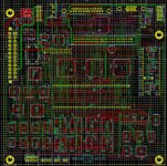
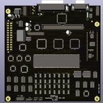
The board will look something roughly like this:
1744758379956.png

Though as you can see there is still most of the routeing work to do so things may get moved around a little

Finally to answer the inevitable question: Why base it on the Plus? why not the IIci? or the SE/30? I chose to base it on the plus simply because it can be built with no original parts, this is intended to be a project build not the fastest possible mac out there.

When finished the design will be fully open source and posted to my GitHub :)
 

MeTheMac

New Tinkerer
Feb 20, 2025
48
7
8
Mars
RetroPods.io
Sounds awesome! I do have a few questions/suggestions. First of all, would it be possible to just have a socket for an IWM instead of the headers? Also, not sure if you've looked into it or not, but what if you attempted to add even more RAM, like 8MB. I beilive their is a workaround for the portable... And finally, what if you used a 16Mhz 68000 instead of the original 8mhz, like the Brainstorm 16Mhz Accelerator? I don't know how feasible any of this is, just suggestions. Anyway, great work!!
 

daanvdl

New Tinkerer
Feb 8, 2023
3
2
3
This is such an awesome project! I especially love how it's completely independent of original/custom parts — that's seriously impressive. The timing couldn’t be better either, with all the great replacements now available like the RTC clone, sound chip replacement, IWM bypass, etc. I'm already looking forward to building one myself once the files are released. Amazing work, and huge thanks for making it open source!
 

max1zzz

Moderator
Staff member
Sep 23, 2021
253
628
93
28
MLB is done! Just need to draw up the riser with the keyboard / mouse / serial ports on it
 

Attachments

  • MLB.JPG
    MLB.JPG
    325.2 KB · Views: 48
  • MLB_3D.JPG
    MLB_3D.JPG
    105.6 KB · Views: 45

Nycturne

Tinkerer
Dec 18, 2024
85
48
18
This is looking great. I’d be very interested in building one of these into one of those sub-5L SFF cases.
 
  • Like
Reactions: MeTheMac

Trash80toG4

Active Tinkerer
Apr 1, 2022
1,058
308
83
Bermuda Triangle, NC USA
Wondering if the Woz has been contacted about releasing his IWM code? He might just do it for a 40th Anniversary Special Edition?
Pincount of ITX PSU Connector confirmed, but very curious about which video bodge connects to the HD15?
 

max1zzz

Moderator
Staff member
Sep 23, 2021
253
628
93
28
The HD15 connector is a standard VGA output generated using GuruThree's Raspberry Pi Pico based converted - you can see the big 40pin footprint for the pico module on the right side of the board. PSU connector is a standard 24pin ATX connector
 

Trash80toG4

Active Tinkerer
Apr 1, 2022
1,058
308
83
Bermuda Triangle, NC USA

max1zzz

Moderator
Staff member
Sep 23, 2021
253
628
93
28
All the non programmables (and the ROM) are soldered down, will get all the PAL's programmed and installed tomorrow. Also still waiting for a pico to arrive as my spare one is AWOL

IMG_4316.jpg
 
  • Love
  • Like
Reactions: bakkus and MeTheMac

Trash80toG4

Active Tinkerer
Apr 1, 2022
1,058
308
83
Bermuda Triangle, NC USA
Very nice! How are the blocks of memory set up in those eight chips so as to look like four 1MB SIMMs on the map? Will the Performer Clone fit or will another Redux form factor project for your board be required? Should be easy, nice that there are no pesky SIMMs in the way. ;)

I keep asking questions, hope you don't mind. Do you have a development topic somewhere or was it a skunkworks project?
 

max1zzz

Moderator
Staff member
Sep 23, 2021
253
628
93
28
RAM is setup exactly as it would be normally would be just without those pesky simm slots :)

The performa clone won't fit as it is, though doing a variation is on my list. Given I expect most people to socket the 68000 when building these it's actually easier to build them this way - just pull the 68k, pop it into a socket on the accelerator then plug that hole thing into the empty socket on the board. No messing with killy clip, soldering headers onto the cpu or anything like that required :)

I keep asking questions, hope you don't mind. Do you have a development topic somewhere or was it a skunkworks project?
Not at all - that's kind of the reason I did a actual thread this time :) The way the project came about was pretty much just me thinking "hey a SMD Plus board would be kind of cool" after the PAL's where reverse engineered and then a little bit later thinking "And why not make it ITX sized?" That's pretty much how all of my projects that aren't just straight RE start 😅
 

Trash80toG4

Active Tinkerer
Apr 1, 2022
1,058
308
83
Bermuda Triangle, NC USA
The performa clone won't fit as it is, though doing a variation is on my list. Given I expect most people to socket the 68000 when building these it's actually easier to build them this way - just pull the 68k, pop it into a socket on the accelerator then plug that hole thing into the empty socket on the board.
That's kinda why I started the 68000 required or not discussion:

No messing with killy clip, soldering headers onto the cpu or anything like that required :)
Might need to make that provision for keeping a 68000 on the system bus via accelerator socket as you said, not sure how the drivers/signalling work. This blurb is from wouter's early look at cloning the original Radius FPD card:

The Bus Master requests the use of the 68000's busses by pulling BR low (Bus Request). The 68000 will then pull BG (Bus Grant) low to indicate that it will release control of the busses at the completion of the current cycle. When the Bus Master is ready to take control it will assert BGACK (Bus Grant Acknowledge) as long as BG=0, AS=1 (the 68000 is not using the bus), DTACK=1 (no external devices are using the bus), and BGACK=1 (no other Bus Master is trying to use the bus).

This I guess would be protocols for the VidCard interacting with the CPU in the pre-Slot Manager interrupt architecture day?

As I all but fail to understand it, the Performer poleaxes the 68000 on boot and it's never addressed again. Wondering if it's needed at all, but for housekeeping?
 
Last edited: