Apple Lisa 3d Case Project

wottle

Active Tinkerer
Oct 30, 2021
897
625
93
49
Fort Mill, SC
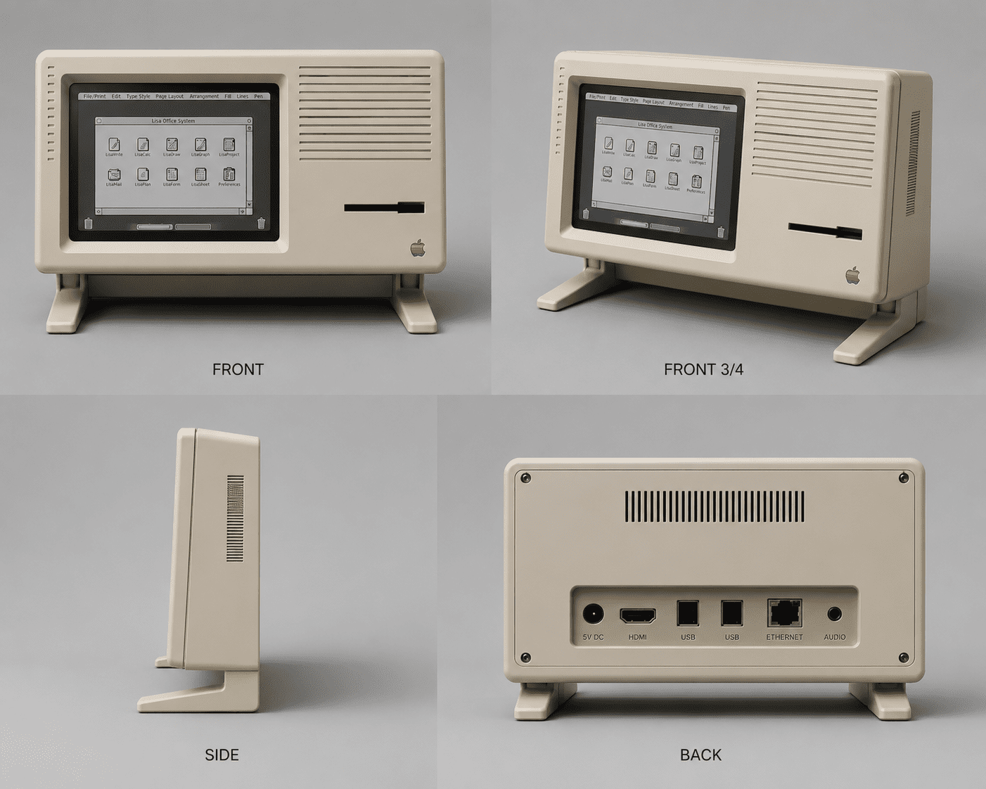
Starting a new thread to further discuss our options here. With the LisaFPGA project, I got the idea I would really love to be stuff the device inside a cool Lisa inspired case (3d printed. I'm no designer, but I got some good inspiration from my friendly AI assistant.
78A4B7B9-B2C3-4CEE-821C-B69307FB65D6.png


Obviously the back ports are no where near correct, the dimensions have some oddities, but this design is something I could really get behind. Others have contributed to the discussion and added some much more accurate models that might be a better approach. But I wanted to pull that discussion over here so we don't interrupt that thread where we should remain focused on the LisaFPGA itself.

Another idea I had was to design a separate case just for the LisaFPGA that would expose all 4 sides of ports, along with push buttons for the board mounted buttons, and maybe openings for the switches. Possibly trying to add slider switches to the top case as well... The larger case with the screen would utilize a 4:3 iPad screen, and you could either pair it with the LisaFPGA case (like a backpack), or maybe an alternative case for a Raspberry pi that ca run the LisaEm emulator.

I know there has been some talk about keeping the floppy port full size. While I think that would be cool, I think it is impractical to stuff a full 3.5" floppy in this case. One design possibility would be to make it like an Apple 2c Plus and have it side mounted. That should change the look of the case versus the original Lisa a bit too much. I was thinking of possibly trying to use it to mount an SD card extension so it is accessible without opening up the case.
 

phunguss

TinkerDifferent Board Vice President
Staff member
Dec 24, 2023
671
571
93
58
Stillwater, MN
I just need something to start with...
Lisa-mini-Beige.jpg

I dug around on the web and found what seems to be a 3D scan of a Lisa 2. I reduced polygons to make it easier to mess with. I shrunk the nose by 50%, and cut 5 inches out of the back. I tried to keep all original angles intact. The Lisa 2 has a 12" CRT vs the 9.7" iPad, so possibly shrinking the bezel and entire project to make it proportional and fit while keeping the floppy hole the correct size.
View attachment 29431
The iPad LCD, original 3.5 floppy drive, and FPGA board (could go vertical or horizontal, extension cables needed for every port) all fit inside with ease.
View attachment 29432
Lisa-mini-guts.jpg
 
  • Like
Reactions: wottle

wottle

Active Tinkerer
Oct 30, 2021
897
625
93
49
Fort Mill, SC
Instead of a floppy drive it should be a floppy emu! Or both!
Yeah, It does have a floppy connector and can be used with floppyemu.

I could replace it with an opening for the floppyEMU. My concern is that it would mess up the look of the original. I'd personally rather have a dummy floppy port, or one that provides access to the SD card for the Profile drive image storage. Eventually, we will likely get floppy emulation as well and the Floppy Emu will become redundant (hopefully). Also, it wouldn't be needed if you are running a Lisa emulator on something like a Raspberry Pi. I definitely don't think we need to keep it full sized when everything else is scaled down because it would throw off the proportions.
 

joevt

Tinkerer
Mar 5, 2023
328
130
43
Real floppy drive is too deep. If you're going to include one, Have the opening on the side (like iMac CD ROM). The front floppy slot can have other stuff - SD card(s)?
https://tinkerdifferent.com/threads/the-apple-lisa-inside-an-fpga.5292/post-46958

Is the ESFLOPPY SD a separate device from the Sony Floppy Drive connector? If not, then a floppyEMU would be redundant? Unless you prefer the floppyEMU UI / features.

Basically, all the connectors and switches will need rewiring to make them accessible.
 

phunguss

TinkerDifferent Board Vice President
Staff member
Dec 24, 2023
671
571
93
58
Stillwater, MN
If you look at a Lisa, every side is a panel, it is not a full single piece like a classic Macintosh. So, you could have alternate panels for the front and right side for people that want a real floppy inside, floppy EMU, or alternate front with SD access.
Lisa-mini-90p-guts.jpg

Just a comparison between original Lisa footprint and a 90% with a thin back. Just playing with ideas, I would likely remodel everything from geometric solids, as this is a 3D scan with lots of defects.
Lisa-mini-90p.jpg
 
  • Love
Reactions: wottle

wottle

Active Tinkerer
Oct 30, 2021
897
625
93
49
Fort Mill, SC
Real floppy drive is too deep. If you're going to include one, Have the opening on the side (like iMac CD ROM). The front floppy slot can have other stuff - SD card(s)?
https://tinkerdifferent.com/threads/the-apple-lisa-inside-an-fpga.5292/post-46958

Is the ESFLOPPY SD a separate device from the Sony Floppy Drive connector? If not, then a floppyEMU would be redundant? Unless you prefer the floppyEMU UI / features.

Basically, all the connectors and switches will need rewiring to make them accessible.
Yeah, I was going to try to expose the connectors as much as possible by making the LisaFPGA it's own case with buttons and openings for the switches on the top, and port openings on all 4 sides. I would try to create a way to mount it somewhat aesthetically to the back of the MiniLisa. It's not going to look nearly as clean, but the alternative is to have inaccessible ports on three sides and only expose USB, which would be clean, but not nearly as functional. In reality, I'm likely only to have USB, power, and HDMI plugged into it. With HDMI being routed internally to the screen, and power also likely to be handled internally to split power between the LCD and the LisaFPGA, this might be OK for most users. It would be a very clean look on the back, with down-facing USB ports and a barrel jack for power being the only wires coming out of it.

I'm curious if other tinkerers are expecting to use the other ports on the LisaFPGA. I think most will use the USB or OG floppy / keyboard ports (those would be the easiest to expose, putting the board with those facing downward towards the ground to make the cables hidden behind the butt of the unit. The Serial ports and the ProFile (parallel?) ports on the top and right side seem much less likely to be used. The Sony floppy port would be the probably next most likely to be used (for a FloppyEmu or physical drive), at least until ESFloppy support is finalized. I would say prioritizing the bottom ports is the right decision.

If you look at a Lisa, every side is a panel, it is not a full single piece like a classic Macintosh. So, you could have alternate panels for the front and right side for people that want a real floppy inside, floppy EMU, or alternate front with SD access.
View attachment 29471
Just a comparison between original Lisa footprint and a 90% with a thin back. Just playing with ideas, I would likely remodel everything from geometric solids, as this is a 3D scan with lots of defects.
I would rotate the board 180 degrees. One, it exposed the USB ports downward, and I think aesthetically that would be ideal. Second, it looks like there is a screen on the board for floppy emulation. If you flip it, that screen (and its buttons) won't be upside down.
 

wottle

Active Tinkerer
Oct 30, 2021
897
625
93
49
Fort Mill, SC
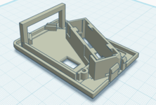
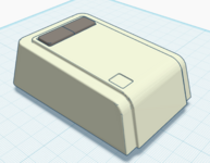
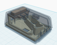
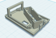
Also, I started trying to see if I could come up with a nice mouse solution. I have 3d printed versions of the Lisa OG Mouse that were meant for a Mac 128k mouse guts. I'm working on a version that you can stuff the guts of a Logitech M185 into.

Screenshot 2026-07-12 at 1.05.47 PM.png Screenshot 2026-07-12 at 1.05.32 PM.png Screenshot 2026-07-12 at 1.07.35 PM.png
I think I have the base completed, but will need to get the mouse in hand to know exactly where the buttons on the board lie and their height so I can make the button's press. I also split the mouse button but need to see how to adjust the attachment because it used to rely on having two hinge points for the one large button. Not sure how the new two button design will work with such a long stand-off between the plastic button and the button on the PCB.
 

Attachments

  • Screenshot 2026-07-12 at 1.05.47 PM.png
    Screenshot 2026-07-12 at 1.05.47 PM.png
    304.4 KB · Views: 2

wottle

Active Tinkerer
Oct 30, 2021
897
625
93
49
Fort Mill, SC
LISA 1 with optical drive! The FDD version looks more substantial, thinness is not a feature.

Why the 9.7" iPad panel limitation?
My rationale for the 9.7" display is mainly that there is a ready supply of relatively cheap 4:3 displays.

You could do what the guy recently did with his full size recreation, but it required him to buy a 15" 16:9 panel and use software to limit the display area, do resolution scaling, etc that isn't as ideal as having a nice, purpose fit panel that let's you use the full display at its native resolution. Of course, I haven't confirmed if the LisaFPGA can output to the 1024x768 native resolution. So when mine arrives I will be hooking it up to the one of my iPad displays to confirm. But trying to make this as straight forward to build. My goal would be to produce something others could recreate. If people have to buy some obscure LCD panel and then spend hours hacking the software to possibly get it to work, it will be a cool one of one display piece. I'd prefer to have these created for more people to enjoy, maybe even producing in "bulk" and sold by someone like @jcm-1.

If there are 12" 4:3 panels that are cheap and easily procured, I'd be open to a mull scale model, but the amount of work to do so could be problematic. The other reasoning I had was with things scaled to a 9.7" display, I think it can be printed on a 350mmx350mm print bed printer. To go full sized, you will either need to print in parts, join together with acetone welding, then deal with a ton of post processing (filler, sanding, more filler, more sanding) to get a decent result. With PLA now coming in retro platinum, you could print in one shot on a consumer printer (I'm considering buying a Creality K2 Plus to give me a large format printer that could print the case in single pieces).
 

phunguss

TinkerDifferent Board Vice President
Staff member
Dec 24, 2023
671
571
93
58
Stillwater, MN
Keeping with the original aesthetics (angles, vents, panels, etc), at 90% scale...
Lisa-mini-plain.jpg

People who want a real 400k floppy could mount it vertical on the right side (label facing you) and only have to replace that one panel. Another panel could be designed for the Floppy emu board and buttons.
Lisa-mini-Floppy.jpg

Keep the entire back panel like the original as one piece to access all ports. Possibly just replace the original ports with holes for cables to come through.
Lisa-mini-backpanel.jpg

Plenty of room for either the LisaFPGA board or a Raspberry Pi project. Throw a power supply brick in the bottom or some other weight to keep a low center of gravity. The gray box is the dimensions of a 3.5 400k floppy in an apple frame.
Lisa-mini-roomy.jpg
 
  • Love
Reactions: wottle

phunguss

TinkerDifferent Board Vice President
Staff member
Dec 24, 2023
671
571
93
58
Stillwater, MN
Makes sense, printing footprint is a major consideration.
Agreed. Some parts could be seamed with minimal visual impact, but the front panel is still an issue. There is room to shrink it further to fit inside a 300x300x400mm build volume of an old CR-10 or 350x350x350 K2 build volume. Further shrinkage may make the 9.7 screen appear disproportionate, but an original 12" to 9.7" conversion should be 80.83 percent.

At 80% the front will fit vertically in a either printer if printed diagonally.
Screen Shot 2026-07-12 at 4.11.19 PM.jpg

The whole unit could be printed as once piece (minus the removable back) if rotated on the side. It would fit in a CR-10, but if the K2 only goes to 350 height, that may not fit.
Screen Shot 2026-07-12 at 4.12.48 PM.jpg
 
Last edited:
  • Like
Reactions: wottle

wottle

Active Tinkerer
Oct 30, 2021
897
625
93
49
Fort Mill, SC
That looks great! I think 80% puts it at somewhere in the neighborhood of 380mm. If we could shave another 40mm off to get it comfortably under 350, I feel like the chances of getting good prints on these increases dramatically. Just not sure what that would do to the rest of the proportions.
 
  • Like
Reactions: phunguss

wottle

Active Tinkerer
Oct 30, 2021
897
625
93
49
Fort Mill, SC
Wow, so cool, and I need it for my soon-to-arrive LisaFPGA! What about using a display other than an iPad?
In theory it will work with other displays, as long as they support HDMI input. I explain my rationale for wanting to use iPad LCD panels here. Basically it comes down to availability, cost, and being able to shrink the case to better support 3d printing without unsightly seams. I still need to confirm how the LisaFPGA works on the 1024x786 display. But I'm interested in hearing what others think. Some guy did just recently 3d print a full scale Lisa and stuffed a 15" LCD that technically fit (it extended past the opening and so it used software on the Raspberry Pi to limit the image to only show on the part of the LCD that was in the opening. Couldn't do that on the LisaFPGA without Alex enabling support for it somehow.

I did find this, which could be an option. I worry about that though because there's a high chance next year you'll be unable to find the same monitor.
 
Last edited: