MAC SE PSU Sony CR-44M Question

FerrisBuehler

New Tinkerer
Mar 1, 2025
8
3
3
72
Texas
Good morning all, I recently watched JDW's recap vid and did the same on my MAC SE. In checking voltages, my 12v lines are in spec but my 5v is coming up to 7v. I adjusted the voltage pot to try to reduce it, but of course, the 12v reduces down to 10.45v or thereabouts.

Question (since I am a newbie but really eager to learn) : What could be the cause of a 5v jumping to 7v? What steps should I perform to track down the problem?
Thanks in advance for your knowledgeable replies!
 

_nec6678

New Tinkerer
Apr 16, 2025
15
7
3
I'm not totally sure, but maybe try checking for shorts or corrosion damage. The voltage between the 12 volt rail and the 5 volt rail would be 7 volts, which may be related to the problem you're having.
 
  • Like
Reactions: FerrisBuehler

_nec6678

New Tinkerer
Apr 16, 2025
15
7
3
Good luck, and be safe. Just remember that if you can't trace down the problem yourself, there are many, many others out there that can certainly help. Or, there are modern replacement PSUs with modern components that might be worth looking at. Please, do let me know how things turn out!
 
  • Like
Reactions: FerrisBuehler

JDW

Administrator
Staff member
Founder
Sep 2, 2021
1,825
1,561
113
54
Japan
youtube.com
I actually wish the POT in my SONY maxed out at 7V so I could pull it down to where the voltage at the motherboard would be 5.05v or there about. My max "no load" voltage, as set via the blue POT, is 5.49v, and you can see that on my spreadsheet here (created when I did the Baby Face PSU review video). The implications of that is that if you have the stock main wiring harness and power-hungry upgrades installed, there's a large voltage drop across that harness, and you always end up with 4.90v or less when measured at the motherboard.

However, your stated "7.0v" is quite high.

You said dropping the voltage via Blue POT brings the 12v line down to 10.45v, but what is the 5v rail voltage, measured at the motherboard, when the 12v rail is 10.45v?

I ask because if your 12v rail drops to 10.45v when you set the POT so the 5v rail measures 5.00V at the PSU (not at the motherboard), that's the wrong way to go about it. You always need to measure at the motherboard due to the large voltage drop across your main wiring harness. The more stock your motherboard, the less voltage drop it will be. But on my machines with upgrades, the voltage drop is always rather large. Or at least, it used to be. I now upgrade my main wiring harnesses in my SE and SE/30 machines using thick 16AWG wires, and you'll find links to RED and BLACK versions of those 16AWG wires in the lower right corner of the spreadsheet page ("SONY PSU" tab) I linked for you above.

You also need to verify STABILITY of your PSU's voltage. For example, does it stay rock solid at 5.0 voltage or does your meter show fluctuations? A scope is far, far better to check stability than a meter because a meter often doesn't update but once every 200ms or so. The scope shows you ever little dip and spike over time.

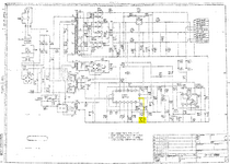
I’ve never heard of the blue “RV251” POTs going bad, and I’m not saying yours is or out of spec either, but if you aren’t making any progress based on what I said above, you could desolder the POT and measure it out of circuit to see if it is indeed still a 1KΩ POT, as per the attached schematic.
 

Attachments

  • SONY-CR44-PSU_POT.png
    SONY-CR44-PSU_POT.png
    200.1 KB · Views: 15

FerrisBuehler

New Tinkerer
Mar 1, 2025
8
3
3
72
Texas
Sorry to be Captain Obvious, but you're not by any chance measuring the voltages under no-load conditions (disconnected from main board)?
Hi JDW! I enjoy your vids! Yes, I was trying that. PSU on worktable and measuring from there very carefully! I was working with ChatGPT to get ideas, voltage expectations, etc. and seeing where that rabbit hole led! I'm not trusting ChatGPT much.

My MAC SE is basic 1MB RAM, 800k Floppy and 20SC Hard Disk. About a year ago, I turned it on and it booted to the last window that I was viewing on it decades prior. Mouse and KB were not working, so I powered down. Then a few months ago, I started wondering if it could be saved and started watching your vids. I hoped that I could learn and attempt to get it going again. I turned it on and then it didn't return to the last screen like before. The hard drive just started making sounds like it was trying to read the heads. I thought I had better turn if off and that is what led me to trying to recap the PSU since I thought it may not be getting good power to all the peripherals. Now, I am doubting my abilities! LOL
 
Last edited:

vtgearhead

New Tinkerer
May 1, 2023
58
23
8
Burlington, VT USA
I'm not an expert on switching power supplies, but many of them require that all rails be loaded in order to guarantee proper regulation. Testing under no-load conditions may well show bogus values. If you don't want to take any chances of damaging the motherboard you'll need to connect a couple of power resistors to provide an equivalent load. Since I've never done this with an SE I'm hesitant to throw out values. Maybe someone else can make suggestions based on experience?
 
  • Like
Reactions: FerrisBuehler

_nec6678

New Tinkerer
Apr 16, 2025
15
7
3
Thankfully, my SE FDHD that has a CR-44 (not sure about the M, might be slightly different) power supply was already apart, since I think that I'm going to do a recap soon. I pulled out the power supply, and checked my voltages without the motherboard or analog board connected. From black to yellow and red, I read about 13.35 and 13.85 volts. From black to both oranges I got 5.32 volts. And finally, from black to green, I read -8.22 volts, which might be the sweep output, but I'm not really a switching power supply expert either!
 
Last edited:

JDW

Administrator
Staff member
Founder
Sep 2, 2021
1,825
1,561
113
54
Japan
youtube.com
… checked my voltages without the motherboard or analog board connected. From black to yellow and red, I read about 13.35 and 13.85 volts. From black to both oranges I got 5.32 volts. And finally, from black to green, I read -8.22 volts
Normal for a no-load test. If you twist the blue POT to max, they probably will go slightly higher. My measurement of 5.49v with the blue POT maxed out is given in my spreadsheet linked earlier.

But through it all, I’ve never measured a no-load voltage as high as 7v on the PSU’s 5V output rail, and that is at the heart of the issue being discussed.
 

FerrisBuehler

New Tinkerer
Mar 1, 2025
8
3
3
72
Texas
Normal for a no-load test. If you twist the blue POT to max, they probably will go slightly higher. My measurement of 5.49v with the blue POT maxed out is given in my spreadsheet linked earlier.

But through it all, I’ve never measured a no-load voltage as high as 7v on the PSU’s 5V output rail, and that is at the heart of the
I went back and cleaned up a few solder areas where I didn't pull away and get the teardrop just right. There may have been a few that maybe hadn't been getting a good connection. I remeasured along with your Sony recap video and now my 5 and 12 volts are normal looking. I copied placing the MM probe as you had for each test (2nd ground wire and the 4th for 5v - orange). Looked good! Then using same ground, tested 12v line. Looked good. However, this weird anomaly happened - I moved the ground probe over to the black wire 1 and the reading went to 20. That was strange. Not convinced that I am ready to connect to Analog and/or MB yet! Thank you all for your input and information!!
 
  • Like
Reactions: _nec6678

JDW

Administrator
Staff member
Founder
Sep 2, 2021
1,825
1,561
113
54
Japan
youtube.com
I'm not sure what to say about the Ground and the 20V reading. As was the case with the oddball 7v measurement, it's clear there's something going on that needs to be figured out, either in terms of proper measuring (probes, contact the probes are making, or the meter itself and/or its battery) or in terms of something possibly being wrong with the PSU in question. But I am glad you seem to be measuring something closer to 5V now, rather than 7v.
 
  • Like
Reactions: FerrisBuehler

FerrisBuehler

New Tinkerer
Mar 1, 2025
8
3
3
72
Texas
I'm not sure what to say about the Ground and the 20V reading. As was the case with the oddball 7v measurement, it's clear there's something going on that needs to be figured out, either in terms of proper measuring (probes, contact the probes are making, or the meter itself and/or its battery) or in terms of something possibly being wrong with the PSU in question. But I am glad you seem to be measuring something closer to 5V now, rather than 7v.
Lol, never a dull moment learning electronics! My background was software development from mainframes, client/server tech, to C# and .Net. Now retired, I love the challenge of learning what I can from all you marvelous electronic geniuses! I can't get enough of y'alls videos! Greatly appreciated!!
 
  • Like
Reactions: JDW

FerrisBuehler

New Tinkerer
Mar 1, 2025
8
3
3
72
Texas
It may have been a weak batter in my MM. I changed them out and my readings are closer now but still a low on Pin 6. Here is what I just measured : PIN 4 was 5.26, PIN 5 was 13.26, PIN 6 was -7.99, PIN 9 was 5.26, PIN 10 was 12.75. These are bench tests on the Sony PSU with no loads. ChatGPT says that my PIN 6 reading may be due to a bad rectifier diode, so I am looking where that may be on the board.

Research is pointing to D277 diode on the -12 path. I'm going to check that out. Learning as I go (I hope!). ;) So, I removed the D277 and the Forward Bias was .52. Reverse got OL as expected. Going to solder diode back in.
 
Last edited:
  • Like
Reactions: _nec6678