LC520 Overclock

Drake

TinkerDifferent Board Vice-President 2023
Staff member
Sep 23, 2021
449
788
93
In regards to the LC520 (68030 @25mhz) it can often be overlooked in favor of the LC575 (68040 @33mhz).
For those unaware these motherboards are a convenient direct swap-in replacement for the sluggish Color Classic motherboard (68030 @16mhz).
*While I am not in favor of cabalistic practices, I do happen to have the models mentioned above and will swap them for fun.*
The following is a simple, quick and easily reversible mod to bump the LC520 from 25mhz to 33mhz (likely what should have been done in factory) but we won't get into Apples intentional sand bagging of systems.
Screenshot_20210923-095850_Photos.jpg

The above resistors are all that stand in the way from unleashing your blazingly fast 33mhz!
simply remove R67, R75, R79.
LC520Mod.jpg

Once completed your LC520 board may have an identity crisis and wish to be addressed as a "Color Classic II" with a 33mhz 68030!
Congratulations Speed Racer, you're at the front of the pack now!
 

JDW

Administrator
Staff member
Founder
Sep 2, 2021
2,238
1,835
113
54
Japan
youtube.com
Amazing info, @Drake!
No ill effects on serial port communication after those resistors are removed?
 
Last edited:

Drake

TinkerDifferent Board Vice-President 2023
Staff member
Sep 23, 2021
449
788
93
Amazing info, @Drake!
No ill effects on serial port communication after those resistors are removed?
Nope! If we look at the actual performa 275 (Color Classic 2) these resistors aren't installed from factory. Further evidence that the LC520 was just the Color Classic 2's big slow brother!
 
  • Like
  • Wow
Reactions: od426819 and JDW

JDW

Administrator
Staff member
Founder
Sep 2, 2021
2,238
1,835
113
54
Japan
youtube.com
Nope! If we look at the actual performa 275 (Color Classic 2) these resistors aren't installed from factory. Further evidence that the LC520 was just the Color Classic 2's big slow brother!
Very interesting indeed!

I'm quite curious as to what the removal of those 3 resistors is doing in the circuit. Do you have a schematic?

The stock Color Classic motherboard is quite similar, but I'm guessing the same thing cannot be done on it. If it could be done, one wouldn't need to swap with an LC520 to get better performance.
 

Mr. Fahrenheit

Tinkerer
Founder
Sep 2, 2021
141
232
43
Very interesting indeed!

I'm quite curious as to what the removal of those 3 resistors is doing in the circuit. Do you have a schematic?

The stock Color Classic motherboard is quite similar, but I'm guessing the same thing cannot be done on it. If it could be done, one wouldn't need to swap with an LC520 to get better performance.

Similar things can be accomplished with the LC575 and allowing it to work at 512x384 resolution, and the LC3 (overclock to 33mhz making it an LC3+), and the LC475/Q605, which can be overclocked easily to 33Mhz from 25mhz.
 
  • Like
Reactions: JDW and Drake

Drake

TinkerDifferent Board Vice-President 2023
Staff member
Sep 23, 2021
449
788
93
Similar things can be accomplished with the LC575 and allowing it to work at 512x384 resolution, and the LC3 (overclock to 33mhz making it an LC3+), and the LC475/Q605, which can be overclocked easily to 33Mhz from 25mhz.
I have done the overclock to a couple pizza boxes as well, a marginal improvement but why not!? On the '040 machines I usually add a heatsink just in case but typically those units don't get too hot.
 

Mr. Fahrenheit

Tinkerer
Founder
Sep 2, 2021
141
232
43
I have done the overclock to a couple pizza boxes as well, a marginal improvement but why not!? On the '040 machines I usually add a heatsink just in case but typically those units don't get too hot.

I bought a LC475 board on eBay last year that had a 128MB SIMM and a full 68040 33mhz on it. I think I paid $125 USD for the board with RAM and the CPU. I recapped it, and cleaned it up, and of course OCd it to the 33mhz the CPU was made to run at. I put heat sinks on all of the chips that warm up, not just the CPU. I then put a 36GB SCSI drive (using a SCA80 to 50 pin adapter) and a PDS ethernet card into it. It's my go to machine besides my Q650.
 
  • Like
Reactions: Fizzbinn and JDW

Fizzbinn

Tinkerer
Nov 29, 2021
237
242
43
Charlottesville, VA
In regards to the LC520 (68030 @25mhz) it can often be overlooked in favor of the LC575 (68040 @33mhz).
For those unaware these motherboards are a convenient direct swap-in replacement for the sluggish Color Classic motherboard (68030 @16mhz).
*While I am not in favor of cabalistic practices, I do happen to have the models mentioned above and will swap them for fun.*
The following is a simple, quick and easily reversible mod to bump the LC520 from 25mhz to 33mhz (likely what should have been done in factory) but we won't get into Apples intentional sand bagging of systems.
View attachment 22
The above resistors are all that stand in the way from unleashing your blazingly fast 33mhz!
simply remove R67, R75, R79.
View attachment 23
Once completed your LC520 board may have an identity crisis and wish to be addressed as a "Color Classic II" with a 33mhz 68030!
Congratulations Speed Racer, you're at the front of the pack now!

Awesome, I had been thinking about whether this might be possible after noticing how similar (seemingly identical) the LC520 (25MHz) logic board is to the LC 550 (33Mhz) and Color Classic II (33Mhz) logic boards (which seem identical themselves except built in VRAM?).

The similarity reminded be of the LC III (25MHz) and LC III+ (33MHz) boards where you just need to move a resistor to turn a III into a III+ and the base LC520/LCIII architectures appear closely related looking at the apple dev notes.

I got a LC520 board in a trade a while back and while it works in the Color Classic (I call it a Color Classic+ :) I definitely will try this out!
 
Last edited:

Fizzbinn

Tinkerer
Nov 29, 2021
237
242
43
Charlottesville, VA
The stock Color Classic motherboard is quite similar, but I'm guessing the same thing cannot be done on it. If it could be done, one wouldn't need to swap with an LC520 to get better performance.

That would be nice, unfortunately you are correct, the Color Classic board's base architecture is from the LC/LC II. The LC III architecture used in the LC 520/550 and CC II, is quite different/improved (32 bit bus, 72-pin SIMM RAM with no 10MB limit, etc.).

One thing that the LC520/550 (and 575 and up) boards have over the LCIII is support for stereo sound, I'm pretty sure I saw a mod for the Color Classic analog board where you can "fill-in" missing components and add second internal speaker to get a Stereo Color Classic!
 
Last edited:

JDW

Administrator
Staff member
Founder
Sep 2, 2021
2,238
1,835
113
54
Japan
youtube.com
I'm pretty sure I saw a mod for the Color Classic analog board where you can "fill-in" missing components and add second internal speaker to get a Stereo Color Classic!
Actually, the Stereo Mod is on the agenda for my Color Classic video series, and I've already acquired the second speaker. But I intend to do the 640x480 and overclocking videos first. Stay tuned! :)
 

JDW

Administrator
Staff member
Founder
Sep 2, 2021
2,238
1,835
113
54
Japan
youtube.com
To @Drake and whomever else might know...

Does the resistor overclock mod increase the clock speed of the CPU and the FPU too? And does it boost the BUS SPEED?

I'm just curious if the resistor mod transforms the LC520 board into an LC550 board, which of course means CPU, FPU and BUS Speed.

Thanks!

1759283292343.png
 

alxlab

Active Tinkerer
Sep 23, 2021
293
323
63
www.alxlab.com
To @Drake and whomever else might know...

Does the resistor overclock mod increase the clock speed of the CPU and the FPU too? And does it boost the BUS SPEED?

I'm just curious if the resistor mod transforms the LC520 board into an LC550 board, which of course means CPU, FPU and BUS Speed.

Thanks!

According to the original modder's docs this mod should make the LC520 board identical to the lC550 board.

https://web.archive.org/web/20160420202025/https://www.thinkclassic.org/viewtopic.php?id=600
 
  • Love
Reactions: JDW

JDW

Administrator
Staff member
Founder
Sep 2, 2021
2,238
1,835
113
54
Japan
youtube.com
@alxlab
Thank you so much for that link!

Uniserver was a significant contributor of helpful info pertaining to our hobby in the past, so I’m pleased to see it was he who provided that crystal clear answer. I’ve actually tried to contact him through the years, but he sadly has become unreachable. I do hope he is doing well.

Anyway, thank you. My question is answered.
 

JDW

Administrator
Staff member
Founder
Sep 2, 2021
2,238
1,835
113
54
Japan
youtube.com
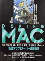
I just learned something new. Even though @Drake and Uniserver both mention the need to remove the 3 resistors R67/75/79, the Japanese book Doping Mac (published in Japan in 1997) says that in addition to those 3 resistors, R80 also needs to be removed...

tempImagestA4zF.png

1760366323285.png


I only have an LC520 motherboard and not the LC550. I sadly cannot find any photo online that shows the solder side of the LC550 board in complete hi-resolution detail. However, it seems that Doping Mac based its article on the fact that when you compare the 520 and 550 boards on the solder side, 4 (not 3) resistors are missing on the 550.

So if anyone out there with an LC550 board (Color Classic II motherboard) could either post a hi-rez photo or otherwise confirm if all 4 resistors are missing, then such would provide further evidence to show what we should do.

The problem is, we don't really know what each of those resistors does, so even though the removal of 3 of the 4 "appears to work" for those like Drake and Uniserver, we don't know what R80 does.
 

Fizzbinn

Tinkerer
Nov 29, 2021
237
242
43
Charlottesville, VA
Here you go:

High Res (as I can do) front and back of my LC 550 logic board. RC67, R75, R79 and R80 not populated:

LC550LB-front.jpg
LC550LB-back.jpg


For similar resolution reference my LC 520 logic board:

LC520LB-front.jpg
LC520LB-back.jpg


Another thought, there are at least two versions of the LC 550/CC II logic board, one with the 3.6 Volt 1/2 AA battery holder and one with the 4.5 Volt PINs and velcro. I've also read somewhere that the CC II version had less built-in VRAM than the LC 550. Perhaps R80 is related to one of those things?
 
Last edited:
  • Love
Reactions: JDW

kefkafloyd

New Tinkerer
May 22, 2023
5
3
3
Massachusetts
www.userlandia.com
Here you go:

High Res (as I can do) front and back of my LC 550 logic board. RC67, R75, R79 and R80 not populated:

View attachment 23758 View attachment 23759

For similar resolution reference my LC 520 logic board:

View attachment 23760 View attachment 23761

Another thought, there are at least two versions of the LC 550/CC II logic board, one with the 3.6 Volt 1/2 AA battery holder and one with the 4.5 Volt PINs and velcro. I've also read somewhere that the CC II version had less built-in VRAM than the LC 550. Perhaps R80 is related to one of those things?
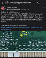
I can also confirm that R80 is missing on my Rev A LC550 logic board for another data point. No idea if R80 is populated on a Rev B board.

Re: LC550/CC II, the LC550 and CC II logic boards are the same logic board. There's no separate part; they're one and the same. All CC IIs had 512K VRAM on board. Apple's official spec guides had a misprint. I don't know if Rev B boards were ever shipped in a CC II before its discontinuation in spring 1994.

 
Last edited:
  • Like
Reactions: JDW

Fizzbinn

Tinkerer
Nov 29, 2021
237
242
43
Charlottesville, VA
I can also confirm that R80 is missing on my Rev A LC550 logic board for another data point. No idea if R80 is populated on a Rev B board.

Re: LC550/CC II, the LC550 and CC II logic boards are the same logic board. There's no separate part; they're one and the same. All CC IIs had 512K VRAM on board. Apple's official spec guides had a misprint. I don't know if Rev B boards were ever shipped in a CC II before its discontinuation in spring 1994.


Really cool article, thanks for sharing! I definitely can see documentation error leading folks to think the LC 550 and CC II logic boards were substantially different when they actually aren't. I do wonder what controls the different gestalt IDs though?

Macintosh LC 520 = 56
Macintosh LC 550 = 80
Macintosh Color Classic II = 83

The resistors affecting CPU speed would explain 520/550, but LC 550/CC II? Something from the chassis? Video resolution from the sense code?

Back to the original question from that article my LC 550 board is Rev B (4.5 Volt PRAM battery) so if you confirmed Rev A (3.6 Volt PRAM battery) then neither have R80 populated.
 
  • Like
Reactions: JDW