PCI Riser Design Rework of GitHub PCIe Riser - Howto?

  • Board Nominations
    Nominations have now closed and the results are available here.
  • Hey Guest, MARCHintosh 2026 is upon us. Check out community projects, join GlobalTalk, and have fun!

Trash80toG4

Active Tinkerer
Apr 1, 2022
1,236
399
83
Bermuda Triangle, NC USA
I've got four different PCI Risers and one based upon PCI on my procrastination list. Haven't done PCB design/production work since the 90s and need help on getting restarted with this.

Has anyone seen a PCI Riser or just a PCI card that I can crib to get started?
Found this one on GitHub and it looks like it could be a good start if PCI not available?

PCIe-riser_v1.jpg


joevt

Tinkerer
Mar 5, 2023
263
103
43
I've got four different PCI Risers and one based upon PCI on my procrastination list.
You are saying the four PCI Risers are not based upon PCI?
You mean they don't connect to a PCI slot? What do they connect to?
The physical form of the connection (PCI slot or otherwise) doesn't matter as long as it has all the PCI signals.
Or do you mean you have four PCI risers. And you also have a fifth PCI riser on your procrastination list?

Has anyone seen a PCI Riser or just a PCI card that I can crib to get started?
You mean PCB schematics?

Found this one on GitHub and it looks like it could be a good start if PCI not available?
That riser is just a pass through - like a cable that passes every signal from the source PCIe slot to the destination PCIe slot.

What do you want your riser to do?

The title of this thread says "PCI Riser Design Rework of GitHub PCIe Riser"
Do you want to make a PCI to PCIe bridge? Or a PCIe to PCI bridge?
You need a PCI to PCIe bridge chip. Some of them work in either direction. There's a list of some chips at:
https://forums.macrumors.com/thread...l-work-in-a-beige-power-macintosh-g3.2303689/
Startech has PCI (32-bit) to PCIe (x1) and PCIe (x1) to PCI (32-bit) bridges. They had a PCI (64-bit) to PCIe (x4) bridge but its no longer available.

The VOGONS forum has threads about AGP/PCI/PCIe bridges.
https://www.vogons.org
 

Trash80toG4

Active Tinkerer
Apr 1, 2022
1,236
399
83
Bermuda Triangle, NC USA
Aha, sorry wasn't clear at all, I'm doing simple, passive right angle risers for PCI Macs and one for the personality card card in Beige G3.

TwinSlot PCI Riser for my 6360 with second slot set back for connector clearance. Also suitable for 5x00 models.
TwinSlot PCI Riser for TAM - with setback for same. Don't own one, but curiosity is just killin' me on that front!
TriSlot PCI RA Riser for my re-cased 6400 BenchMac
QuadSlot RA Riser for same using a signal pickup card in ComSlot II for the fourth PCI Slot.
- setup like PCI signal jumper card card below. Already tested, it works OK so far, curiosity again. :rolleyes:

TAM/6500/5500 are limited to a pair of PCI Slots as the Graphics Subsystem sit on the third setup.

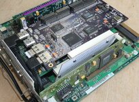
Personality Card RA(left angle?) Riser to flop the Personality Card over at the top of my 2UBG3 build as such:

2UBG3-00.JPG


Intend for riser to flop the card over as does the cable riser, but placing the card opposite and directly next to the top PCI Card. That leaves room for a multifunction 5.25" bay to the left of the serial ports and maybe a 3.5" bay directly under the skinny Personality Card.

Have ten thruhole connectors for (minimum $) order on the way for this one. Thruhole PCI Connectors should be readily available at reasonable pricing for the rest of my designs.

The edge card section of the PCIe card above and traces (minus resistors) would terminate in thruholes for PCI and Personality Card connectors.

If only Gerbers are available on GitHub, can they be imported into a PCB design package? I want to learn to do this in KiCad.
- might that program import gerbers into library type elements?
- might another package be required to convert them?
- might KiCad have the PCI Card edgecard and thruhole slot models for PCI design ready to use?

Total n00b on this kind of workflow. The extent of my 80s/90s PCB work was done by designing PCBs in a sign graphics package for 2x plotter cut Rubyliths sent out for Process Camera work at the fab.

I've routed most everything manually in AI. Cardboard prototypes have been made, connectors installed and everything tested for fitment. Just need to get the designs into something like KiCad for sending out for production.

Any help will be greatly appreciated.
 
Last edited:

luRaichu

New Tinkerer
Oct 29, 2023
7
5
3
The PCIe riser design you linked is just a normal KiCad project that can be opened right up. Though, I'm not sure why you would bother with it when you really want to work with PCI.
Maybe, an illustration or sketch of the board you want would help!
I see KiCad has a PCI edge connector footprint built-in, but not one for a PCI slot. No problem, it can be found online.
I'd be happy to design a board, but, if you teach a man to fish...
 

Trash80toG4

Active Tinkerer
Apr 1, 2022
1,236
399
83
Bermuda Triangle, NC USA
. . . his hands and clothes always smell fishy!

I'll look around for the AI files locally. They're posted all over the place at the MLA. :rolleyes:


edit: took a look around and apparently they're here. Found my visual AI schematic. My brain does pictures, doesn't grok schematics.
Cardboard fitment prototypes here:

Does this explain a bit about what I'm doing?
 
Last edited:

Trash80toG4

Active Tinkerer
Apr 1, 2022
1,236
399
83
Bermuda Triangle, NC USA
Cardboard prototype installed and cabled up in my 6360 drawer shows how the setback works:

-TwiSlot-TEMPOtrio-6360-Top-Right-Oblique-2p-half-size.jpg

Multiple views from different angles are in thread.

TAM TwinSlot Riser is up here at the top:
TwinSlot-502.jpg

6360/5x00 TwinSlot Riser's down here at the bottom.

In between, the TAM card is seen as an overlay of the OEM card scan. There's scootch room in the FatBack for this to work, haven't had anyone test fitment as yet.
 

Attachments

  • -TwiSlot-TEMPOtrio-6360-Top-Right-Oblique-2p.jpg
    -TwiSlot-TEMPOtrio-6360-Top-Right-Oblique-2p.jpg
    484.7 KB · Views: 34
Last edited:

joevt

Tinkerer
Mar 5, 2023
263
103
43
I'll look around for the AI files locally.
visual AI schematic
What's an AI file or an AI schematic? Adobe Illustrator? (not related to artificial intelligence)

Still not sure why the thread title mentions PCIe. Is it just because the GitHub describing the PCIe riser is the only PCB design example (or the first) that you could find? PCIe and PCI slots and card edges have differences. For one, they have different pin pitch but you probably know all that.

Those other threads you linked describe the design of the risers. The purpose of this thread is to convert the design to something that can be used to create a PCB such as by using PCBWay or JLCPCB?
 

Trash80toG4

Active Tinkerer
Apr 1, 2022
1,236
399
83
Bermuda Triangle, NC USA
Yep, that PCIe card was the only thing useful that turned up when I signed up and searched GitHub today. Hoping someone might point me to a better example. Nice to find out that KiCad has the PCI edgecard connector in its library. PCIe has the same pitch as PCI from what I've seen, no?

Sorry, AI has always meant Adobe Illustrator, times they are a changing. I use Illustrator to do whatever artwork is needed for my projects. Guess I'll have to remember to type out "Illustrator files."

Correct, I'm trying to get started on using KiCad to send files out to a board fab.
 

joevt

Tinkerer
Mar 5, 2023
263
103
43
PCIe has the same pitch as PCI from what I've seen, no?
M.2 is 0.5 mm.
mPCIe is 0.8 mm.
PCIe is 1.0 mm.
PCI is 1.27 mm (0.5 inch).
ISA is 2.54 mm (0.1 inch).
So make sure you choose the correct setting.

Correct, I'm trying to get started on using KiCad to send files out to a board fab.
I've never tried Kicad.
Googled "using kicad for pcbway". Found some videos. There's a Kicad plugin for PCBWay.
There's a PCBWay blog post with some basic steps:
https://www.pcbway.com/blog/help_center/Basic_instructions_for_using_KiCad.html
 

luRaichu

New Tinkerer
Oct 29, 2023
7
5
3
PCBWay is overpriced. JLCPCB is the best value fab at this time.
Don't need fab specific plugins. Just export your PCB design to Gerber files and upload to fab...
So, you want the 6360/5x00 TwinSlot Riser to exist.
Would be helpful to know the value of the resistors & capacitors used in the TriSlot-ABC picture.
What's the part # of the through-hole PCI slots you bought?
I want to make PCB...
 

Trash80toG4

Active Tinkerer
Apr 1, 2022
1,236
399
83
Bermuda Triangle, NC USA
Thanks! Looks like a good start. I think I'll do the Personality Card riser first. I have seven or eight desktops with cards that someone gave me. I don't care at all if I blow some up after I cull the worst boards and their A/V cards.


edit: thanks so much for the PCIe/PCI pitch info. Haven't card nor board that uses them.
 
Last edited:

Trash80toG4

Active Tinkerer
Apr 1, 2022
1,236
399
83
Bermuda Triangle, NC USA
Would be helpful to know the value of the resistors & capacitors used in the TriSlot-ABC picture.
What's the part # of the through-hole PCI slots you bought?

Resistor's value is from Apple's docs, those I can get from the book or find in one of my threads..
Little brown capacitor values, no clue. ISTR needing a special meter (ESR?) to measure capacitance or can I do that with a multi-meter?
Haven't ordered PCI connectors yet, incoming parts are for the Personality Card. Those are hard to come by.

Maybe another member has a 6x00 riser and requisite meter for the capacitance value?

I want to make PCB...
Sweet! 😁
 

luRaichu

New Tinkerer
Oct 29, 2023
7
5
3
Resistor's value is from Apple's docs, those I can get from the book or find in one of my threads..
Let me know when you find them... Also, I think the capacitors are just for decoupling? If so capacitance value is not critical and can be assumed.
Please check this. If they are decoupling then the anode (+) will be connected to Vcc and the cathode (-) goes to GND.
Once this and the resistor values are confirmed I can begin drawing proper schematics.

I know that the 2nd slot in the riser is set forward by 2cm. What's the vertical distance supposed to be from the edge connector to the 1st slot?
So, edge connector is wired straight-through to the 1st slot (A) and the 2nd slot is setup as B?
 

Trash80toG4

Active Tinkerer
Apr 1, 2022
1,236
399
83
Bermuda Triangle, NC USA
Let me know when you find them...
Will do.
Also, I think the capacitors are just for decoupling? If so capacitance value is not critical and can be assumed.
Please check this. If they are decoupling then the anode (+) will be connected to Vcc and the cathode (-) goes to GND.
Pretty sure that's the case, but not buzzed. Been procrastinating about desoldering a board to check the traces.
Once this and the resistor values are confirmed I can begin drawing proper schematics.
Sounds good.
I know that the 2nd slot in the riser is set forward by 2cm. What's the vertical distance supposed to be from the edge connector to the 1st slot?
Setback from backplane? Gotta pull the contraption out to verify all the measurements. Everything is on a .1" DIP thruhole grid.
So, edge connector is wired straight-through to the 1st slot (A) and the 2nd slot is setup as B?
Yep, electrically identical to the 6x00 Riser! When you have this board finished, all that needs to be done would be to drop the edgecard connector a bit and that'd be the TwinSlot TAM Riser.

Where are you located? If U.S. I can send you riser examples.
 

Trash80toG4

Active Tinkerer
Apr 1, 2022
1,236
399
83
Bermuda Triangle, NC USA
Fastest knuckle dragging Neanderthal method connector desoldering job to date! Previous connector removal was EuroDIN-120.

6400-PCI-Riser-Sans-Connector.JPG

Hacksaw beats Hot Air hands down!

TwinSlotRiserProto2-c.JPG

Less confusing illustration with outline of 6360/5x00 card in relation to TAM Riser outline.
Intend to replace pic with mirrored image to match photo.\

TAM-PCI-Riser-0-half-size.jpg


PCI-Interrupt-1996.jpg


Resistive IDSEL connection and bypass caps done on logic board for Slot A.

Will be setting Slot B back another .1" unit to the rear for better cable clearance.

-TwiSlot-TEMPOtrio-Cable-Exit-TAM-2p-half-size.jpg


-TwiSlot-TEMPOtrio-Cable-Run-TAM-Path-2p-half-size.jpg


White template represents side panel of TAM. USB/FireWire card replaces 10bt NIC/Riser. USB (or FireWire?) NIC beats it hands down. Been wondering if USBC connection on risers could provide power for additional cards and provide jumper for USB1 connection to USB/FW card in additional Slot(s)?

Power/Cooling budget of 6360/5x00 might suffice for a TwinSlot Riser, but TAM is bleeding edge case. Powered USBC Hub could provide power for both (all) slots in any case? PTO provision on Riser could be put to good use in TAM for just about anything? Jumper select for power connection would be required.

________________________________________________________________________________________________

@luRaichu much of the above is extraneous to your PCB layout, just trying to get everythingrelater to the various risers into one new, simplified thread to keep my head as on track as it ever gets. 🤪 I'm laying the groundwork for further developments. Will re-title topic and clean up initial post.

One major request would be to do the resistor and capacitors in thruhole components instead of surface mount. That'll make hand soldering much easier and set the stage for doing a wave soldered batch of complete boards if enough interest.
 
Last edited: