Anyone wanna help me troubleshoot my Simasimac Reloaded SE/30 board?

Steve Rieck

New Tinkerer
Mar 24, 2023
36
21
8
KNOWN SO FAR
CPU - Working Correctly (Swapped from good board)
ROM SIMM - Working Correctly (Swapped from good board)
RAM SIMMS - Working Correctly (Swapped from good board)
VIDEO ROM - Working Correctly (Swapped from good board)
VIDEO PALS - Working Correctly (Swapped from good board)
VIDEO RAM - Working Correctly (Swapped from good board)
RAM Diodes - Corrected and Tested (one of Colin's boards)
New FPU
New CAPS
RESET Switch functioning correctly
RESET Circuit intact an operating correctly
NMI Switch has NO effect but is mechanically ok
GLUE Chip Continuity - All pins checked and ok
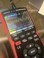
All Clock signals are present and correct.
I am NOT getting square waves on the ROM Adnress lines (Not walking)

UNKNOWN
All Address Line Continuity (Checking this next)
All Data Line Continuity (Checking this next)
Possibly damaged GLUE Chip - Pulled from bombed board
Damaged ASC or UB11 ? No sound at all

OTHER
Have a nice mildly bombed IICX board on the way for parts

Thanks for any thoughts!
 

GreenBar0n

Tinkerer
Dec 22, 2025
104
65
28
East Bay Area, CA
According to the Simasimac Repair Guide, everything starts with the ASC UE10 chip, the Reset line is released from there before anything else will start. I would verify the Reset line on UE10 is operating correctly, first.

SE30 Boot.jpg


I would then check that the Data lines have continuity from the CPU to the ROM slot, with the ROM SIMM removed. The numbering of the ROM slot can be confusing, as the Data lines are listed in order, but the ROM slot pins skip around quite a bit, it's easy to get lost or confused, have to pay close attention to the Matrix pin order:

Data Matrix.jpg


If all those signals are present, then check the Address line Matrix, from CPU to ROM slot.

Then I'd worry about the Clock signals and walking the bus.
 
  • Love
Reactions: Steve Rieck

Steve Rieck

New Tinkerer
Mar 24, 2023
36
21
8
Just went through every single pin for every single address and data line per the schematic redraw matrixes.... exhausting.

Everything checks ok.
 
  • Like
Reactions: GreenBar0n

Steve Rieck

New Tinkerer
Mar 24, 2023
36
21
8
The data line signals on the video ROM and video RAM get this mess instead of nice square waves... I think it's a bad glue chip or maybe UH7.
 

Attachments

  • IMG_7995.jpeg
    IMG_7995.jpeg
    1.1 MB · Views: 3
  • Like
Reactions: GreenBar0n

Steve Rieck

New Tinkerer
Mar 24, 2023
36
21
8
unfortunately getting the same trashy signal. so I think this clearly indicates something more serious than a bad ram diode or UH7 pal etc? That's why I'm suspecting the glue which came off a badly bombed board. Fortunately, I have a iicx board in the mail.
 

Attachments

  • IMG_7998.jpeg
    IMG_7998.jpeg
    1.1 MB · Views: 6
Last edited:

Froggy814

New Tinkerer
May 6, 2026
7
1
3
Didn't Colin from This does not compute have to add a bodge wire that they added from the factory that wasn't fixed on the reloaded board, did you add it?
 
  • Like
Reactions: GreenBar0n

Steve Rieck

New Tinkerer
Mar 24, 2023
36
21
8
Didn't Colin from This does not compute have to add a bodge wire that they added from the factory that wasn't fixed on the reloaded board, did you add it?
that's a great point. I do remember seeing that in the video. It's on one of the video pals I recall. When I was previously working on this port I remember confirming that this board didn't need it for some reason. But I'll double check
 

Steve Rieck

New Tinkerer
Mar 24, 2023
36
21
8
Good point, never asked if this was a V5 Reloaded board.


@Steve Rieck , In the first post it says all your clock signals are good, you are getting good square waves with your scope in other areas?
Here is what Y1 for example looks like on the scope. The frequency looks correct but it's definitely not a square wave. I assume it is supposed Sorry I'm just learning this stuff.
IMG_7999.jpeg
 
  • Like
Reactions: GreenBar0n

GreenBar0n

Tinkerer
Dec 22, 2025
104
65
28
East Bay Area, CA
Hard to believe the GLUE chip is bad, but with the correct clock signals at the those locations you showed above, the ROM slot should also be showing square waves.

Have the VIA chips both been toned out and have complete continuity? Those are the link between the CPU, GLUE and ROM slot.
 
  • Like
Reactions: Steve Rieck

Steve Rieck

New Tinkerer
Mar 24, 2023
36
21
8
Hard to believe the GLUE chip is bad, but with the correct clock signals at the those locations you showed above, the ROM slot should also be showing square waves.

Have the VIA chips both been toned out and have complete continuity? Those are the link between the CPU, GLUE and ROM slot
interesting. Thank you so much for your help! I'm gonna check out all of this tomorrow.
 
  • Like
Reactions: GreenBar0n