Update: it's fully working. Full writeup below with final measured values, in case it's useful to anyone else attempting this.
Background: running a Macintosh Plus logic board (1MB RAM, booting off BlueSCSI) off a Macintosh SE's analog board, PSU, and CRT, in place of the Plus's own analog board.
What worked immediately: Video and HSYNC connected directly, no inversion, no extra circuitry.
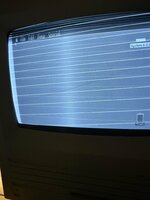
The problem: with VSYNC also connected directly, the picture was otherwise correct (right proportions, legible text) but showed persistent horizontal lines across the top of the frame — looked like unblanked vertical retrace.
Diagnosis: scoped VSYNC directly at the connector on both a known-good SE logic board and the Plus logic board, same test point, for a real comparison. Results:
- Plus VSYNC low (retrace) pulse width: ~900µs
- SE's own native VSYNC low pulse width: ~200µs
So the Plus holds VSYNC low about 4.5x longer than what the SE's analog board (TDA1170-based vertical deflection) is normally fed. Makes sense given the SE and later compacts use the TDA1170 IC for vertical deflection, while the Plus/128K/512K use a completely different, older discrete op-amp/transistor vertical circuit — horizontal/video timing is apparently very close to identical across the family, but vertical isn't.
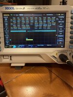
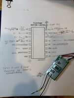
Fix: built a 74HC123 dual retriggerable monostable multivibrator to reshape the Plus's VSYNC pulse down to ~200µs before it reaches the SE analog board. Final circuit and measured values below (photo of the schematic/board attached). Built on the SO16 (D-package) variant, hand-soldered to a SOP16 breakout — pinout is identical to the standard DIP-16.
74HC123 wiring:
- Pin 1 (1A): Plus VSYNC input, through a 1kΩ series resistor (the Plus's VSYNC showed real negative undershoot on the scope, down to about -2 to -3V — this resistor protects the chip's input clamp diodes)
- Pin 2 (1B): tied to +5V (enables falling-edge triggering via pin 1)
- Pin 3 (1RD): tied to +5V (holds channel out of reset)
- Pin 4 (1Q̄, active-low output): shaped VSYNC output, feeding the SE's VSYNC input through a current-limiting pot, final measured value 3.533kΩ
- Pin 8: GND
- Pin 13 (1Q, active-high): no connection — this is the inverted-sense complement of pin 4, not needed here
- Pin 14 (1CEXT): one leg of a 10nF ceramic cap, other leg to pin 15 (no ground on this pin — followed TI's application-note wiring rather than the alternate "ground the Cext pin" convention some other manufacturers show; worked correctly as-is)
- Pin 15 (1REXT/CEXT): other leg of that same 10nF cap, plus the timing resistor network to +5V — 10kΩ fixed resistor in series with a multi-turn 50K pot, final measured total 46.76kΩ (10kΩ fixed + 36.76kΩ pot) - you use this 50K pot to tune the VSYNC low pulse width to ~200µs
- Pin 16 (VCC): +5V with a 0.1µF bypass cap close to the chip
- Channel 2 (unused): pins 6, 7, 9, 10, 11 grounded; pins 5, 12 left unconnected
Current-limiting on the output (pin 4 → SE VSYNC) was necessary because the TDA1170's sync input is spec'd for roughly 500µA and the 74HC123's output is a much stronger driver. Tested 20kΩ and 10kΩ first — both resulted in a static bright horizontal line (not enough current for the TDA1170 to lock onto sync, so vertical deflection wasn't sweeping). Final working value: 3.533kΩ.
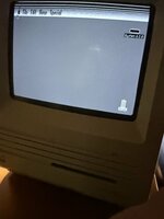
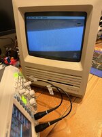
Result: fully legible System 6.0.8 desktop, correct proportions, no artifacts, stable over extended run time. Photos attached, including the scope traces showing the shaped 200µs pulse and the finished board.
litriSE