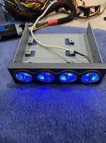
The Antec TP-II 550 is a powerful power supply that was originally offered in two variants: one with the TrueControl panel and one without. The TrueControl panel was a unique feature that mounted in a 5.25" drive bay and provided manual voltage adjustment through four potentiometers (pots) for the 12V, 5V, 3.3V, and fan voltage rails.
If you have the version without the control panel—or if you've lost the original panel—you may have noticed a significant problem: the power supply defaults to voltages that are barely within ATX specification, with all rails running quite low. This makes the PSU difficult to use reliably without the control panel.
Fortunately, with some community help and reverse engineering, it's possible to build a simple replacement control circuit that restores full functionality to this beast of a power supply. This guide will walk you through creating your own TrueControl replacement using readily available components.
Credits
This project was made possible thanks to the collaborative efforts of several community members:
Connector:
Optional:
Step 1: Prepare the Potentiometers
For each of the four potentiometers:
For a temporary solution, I've hot glued the assembly directly to the power supply casing. I may do a PCB in the future, but for now... this'll do
While this may not be as elegant as the original TrueControl panel, it's a functional and cost-effective way to restore your Antec TP-II 550 w/ Truecontrol to full working order. The total cost in components is minimal, and the assembly is straightforward enough for anyone comfortable with basic soldering.
Happy building, and enjoy your newly functional power supply!
If you have the version without the control panel—or if you've lost the original panel—you may have noticed a significant problem: the power supply defaults to voltages that are barely within ATX specification, with all rails running quite low. This makes the PSU difficult to use reliably without the control panel.
Fortunately, with some community help and reverse engineering, it's possible to build a simple replacement control circuit that restores full functionality to this beast of a power supply. This guide will walk you through creating your own TrueControl replacement using readily available components.
Credits
This project was made possible thanks to the collaborative efforts of several community members:
- @zigzagjoe and @mmu_man - Identified the connector type used by the TrueControl panel
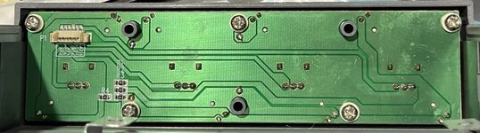
- Mr. Cacodemon (Power Supply Central Discord) - Provided PCB photos, pinouts, and pot measurements from an actual control panel
What You'll Need
Potentiometers (1/2 watt or 1/4 watt):- 12V rail: 4-600Ω pot (1kΩ pot works well)
- 3.3V rail: 4-1500Ω pot (2kΩ pot works well)
- 5V rail: 4-1500Ω pot (2kΩ pot works well)
- Fan line: 5400-5600Ω pot (5kΩ pot works well)
- Example pots on Amazon
Connector:
- Molex PicoBlade connector (available from DigiKey or Amazon)
- Amazon bundle option
Optional:
- 330Ω SMD resistors for LEDs (if you want indicator lights)
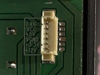
TrueControl Pinout
| Wire Color | Function |
| Yellow | 12V |
| Brown | 3.3V |
| Black | Ground (Vgnd) |
| Red | 5V |
| Green | Vcc (LED power only) |
| Blue | Fan |
Assembly Instructions
Step 1: Prepare the Potentiometers
For each of the four potentiometers:
- Identify pins 1, 2, and 3 on the pot
- Connect pins 2 and 3 together—these will be your common ground connection
- Pin 1 will be your voltage adjustment output
- Connect the joined pins 2 & 3 from all four pots to the Black (Ground) wire on the connector
- Connect pin 1 of each pot to its corresponding wire:
- 12V pot → Yellow wire
- 3.3V pot → Brown wire
- 5V pot → Red wire
- Fan pot → Blue wire
- The Green (Vcc) wire is only needed if you're adding LED indicators
- Connect your assembled control circuit to the power supply connector
- Use your BIOS readings or a multimeter to check voltages
- Adjust each potentiometer until voltages are within proper ATX specifications.
- Fan voltage: Adjust to preference, i set mine to about 7v. This adjustment also adjusts the fan-only molex connectors too!
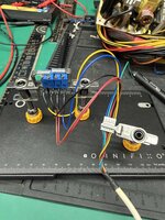
For a temporary solution, I've hot glued the assembly directly to the power supply casing. I may do a PCB in the future, but for now... this'll do
While this may not be as elegant as the original TrueControl panel, it's a functional and cost-effective way to restore your Antec TP-II 550 w/ Truecontrol to full working order. The total cost in components is minimal, and the assembly is straightforward enough for anyone comfortable with basic soldering.
Happy building, and enjoy your newly functional power supply!