So, I’ve been working on a few of the last of the machines I picked up late last year. One of them was a battery bombed 650 that had a damaged SIMM slot. Unfortunately, I think I used too much heat and damaged some traces trying to remove that 72 pin socket. I did finally get it out, and ordered a new one from mouser.
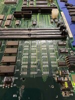
I got it reinstalled, and repairs two traces that were damaged, and still wasn’t able to get a boot chime. That’s when I realized the board was missing some chips that were there on my other Q650 / Q800 board. U18 and U22 were removed from the board. As was RP7. So I pulled the chips from another battery bombed board and was able to get a boot chime, followed by a sad Mac. Some of the memory chips near the battery looked a bit suspect, so I removed one of the banks of memory chips, U44, u45, U49, U50, U53, U54, U60, and U61. I cleaned and tested the traces I could see and they seemed good. And I got a boot chime and no sad Mac. I also got video out, but it was corrupt.
it seems like I’ve lost some colors, or the colors are scrambled. I have a green mouse, and vertical pink dotted lines down the screen. This doesn’t change with putting in known good vram chips installed or not

The other issue is that I obviously have half the built in memory with the chips I removed. I can out ram sticks in slots 1 and 3 and they work great. But if I RAM in slot 2 or 4, the sad Mac chime returns. Did I miss a damaged trace for slot 2/4 or will it not work with the on board RAM chips missing?
Other things seem to work fine. my ADB mouse works when plugged and I was able to boot from a BlueSCSI.
Where else do I need to look around for the corrupt video issue? Should I be concerned that the chips were slightly different for U18 / U22? They were still F245 chips. Just seemed to be Motorola branded. Also, the resistor pack at RP7 was a bit different, but I’m wondering if the 9247 vs 9316 markings were a date code? 1992 or 1993 would make sense for these, I think. All the chips that I believe are on board video ram (U20-U32) seem to be in good shape as do the traces nearby.
Appreciate any help or insight yall can provide!


I got it reinstalled, and repairs two traces that were damaged, and still wasn’t able to get a boot chime. That’s when I realized the board was missing some chips that were there on my other Q650 / Q800 board. U18 and U22 were removed from the board. As was RP7. So I pulled the chips from another battery bombed board and was able to get a boot chime, followed by a sad Mac. Some of the memory chips near the battery looked a bit suspect, so I removed one of the banks of memory chips, U44, u45, U49, U50, U53, U54, U60, and U61. I cleaned and tested the traces I could see and they seemed good. And I got a boot chime and no sad Mac. I also got video out, but it was corrupt.
it seems like I’ve lost some colors, or the colors are scrambled. I have a green mouse, and vertical pink dotted lines down the screen. This doesn’t change with putting in known good vram chips installed or not
The other issue is that I obviously have half the built in memory with the chips I removed. I can out ram sticks in slots 1 and 3 and they work great. But if I RAM in slot 2 or 4, the sad Mac chime returns. Did I miss a damaged trace for slot 2/4 or will it not work with the on board RAM chips missing?
Other things seem to work fine. my ADB mouse works when plugged and I was able to boot from a BlueSCSI.
Where else do I need to look around for the corrupt video issue? Should I be concerned that the chips were slightly different for U18 / U22? They were still F245 chips. Just seemed to be Motorola branded. Also, the resistor pack at RP7 was a bit different, but I’m wondering if the 9247 vs 9316 markings were a date code? 1992 or 1993 would make sense for these, I think. All the chips that I believe are on board video ram (U20-U32) seem to be in good shape as do the traces nearby.
Appreciate any help or insight yall can provide!