Hi all,
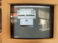
I just performed the VGA mod on my CC as outlined in JDW’s excellent video. At first, it didn’t seem like it was working. The image was squished horizontally and no amount of adjustments worked. It took me a bit to realize that it was actually in 67Hz mode! The sense lines appeared to be reporting the display as a “Multiple Scan Display”.
I checked my points over and over again. All the solder points checked out fine, and the pins that needed to be isolated were surely isolated.
This is where it gets weirder. Against my better judgment, I decided to try the old school HiRes mod to see if the screen would fill correctly with the refresh rate at 67Hz, and as expected, it did. So I adjusted the monitor and figured I was going to do need to do the improved version of the Hires mod.
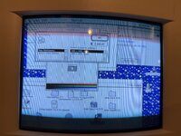
That was until I restarted and then the screen changed to 60Hz! Now the screen I painstakingly adjusted was off the screen. So I adjusted it back again. But sure enough, when I came back later after it was off for a while, it was back to 67Hz! And then when I used it for a half hour and needed to restart, it switched back to 60Hz!
I am at a loss. FWIW, I did do a full cap kit before the mod.
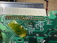
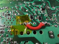
Does anyone have any idea what might be happening here? I’ve attached some pictures of the VGA mod (before I moved the horizontal coil leg over to 84V), and the display showing both 67 Hz and 60 Hz options.
I just performed the VGA mod on my CC as outlined in JDW’s excellent video. At first, it didn’t seem like it was working. The image was squished horizontally and no amount of adjustments worked. It took me a bit to realize that it was actually in 67Hz mode! The sense lines appeared to be reporting the display as a “Multiple Scan Display”.
I checked my points over and over again. All the solder points checked out fine, and the pins that needed to be isolated were surely isolated.
This is where it gets weirder. Against my better judgment, I decided to try the old school HiRes mod to see if the screen would fill correctly with the refresh rate at 67Hz, and as expected, it did. So I adjusted the monitor and figured I was going to do need to do the improved version of the Hires mod.
That was until I restarted and then the screen changed to 60Hz! Now the screen I painstakingly adjusted was off the screen. So I adjusted it back again. But sure enough, when I came back later after it was off for a while, it was back to 67Hz! And then when I used it for a half hour and needed to restart, it switched back to 60Hz!
I am at a loss. FWIW, I did do a full cap kit before the mod.
Does anyone have any idea what might be happening here? I’ve attached some pictures of the VGA mod (before I moved the horizontal coil leg over to 84V), and the display showing both 67 Hz and 60 Hz options.