Hi there fellow Lisa (and other) aficionados!
I have started the journey of repairing a heavily battery bombed Lisa 2 (Frankenstein/modified model, it has an internal hard drive + a parallel port). Right now I am tackling the motherboard which has most of the damage, hoping I can get it back to working condition. Another forum member (rdmark, see the excellent write up of that member's repair journey) already gave me a few good tips and resources for replacement parts, and I've tried to do a bunch of research on filling in the gaps (I consulted this excellent forum, applefritter, 68kmla, and lisalist2 for the most part, amongst some more random and general google searches). Things I have done so far:
I found the (some) schematics here but I'm a) a complete novice when it comes to identifying passive components (or anything else to do with electronics, for the most part), b) no expert in reading schematics (I sometimes can't even tell the difference between a capacitor and an ibuprofen tablet") ) , and c) if I'm reading this correctly, I'm not sure how accurate it is as there's some capacitors mentioned (specifically C3, C4) that don't exist on my version of the board, and it definitely seems to omit some of the parts I'm after (unless I missed something obvious).
) , and c) if I'm reading this correctly, I'm not sure how accurate it is as there's some capacitors mentioned (specifically C3, C4) that don't exist on my version of the board, and it definitely seems to omit some of the parts I'm after (unless I missed something obvious).
Specifically:
Thankfully the remaining boards are in much better condition, so I'm hopeful to get this back into working order soon (the condition of the hard and floppy drive remains to be verified)!
Thanks!
I have started the journey of repairing a heavily battery bombed Lisa 2 (Frankenstein/modified model, it has an internal hard drive + a parallel port). Right now I am tackling the motherboard which has most of the damage, hoping I can get it back to working condition. Another forum member (rdmark, see the excellent write up of that member's repair journey) already gave me a few good tips and resources for replacement parts, and I've tried to do a bunch of research on filling in the gaps (I consulted this excellent forum, applefritter, 68kmla, and lisalist2 for the most part, amongst some more random and general google searches). Things I have done so far:
- vinegar bath and scrubbing
- needed to drill out a few screws as they were completely rusted over and could not be removed otherwise
- removed the badly corroded parallel, video, mouse and serial connectors (still working on the reset button which is stubborn)
I found the (some) schematics here but I'm a) a complete novice when it comes to identifying passive components (or anything else to do with electronics, for the most part), b) no expert in reading schematics (I sometimes can't even tell the difference between a capacitor and an ibuprofen tablet
) , and c) if I'm reading this correctly, I'm not sure how accurate it is as there's some capacitors mentioned (specifically C3, C4) that don't exist on my version of the board, and it definitely seems to omit some of the parts I'm after (unless I missed something obvious).Specifically:
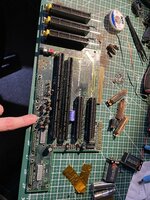
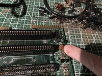
- what are the black cylindrical and the round ceramic looking components marked L1-L11 (where my finger's pointing); I've seen some of them mentioned as inductors (with one 68kmla threadidentifying their value as 10µH) - am I right in thinking those are the black cylindrical components?
- What are the ceramic disks that seem to accompany them 1:1? The writing on them says (provisional until I get something to magnify them better): COIM 25R (I've seen that spec used for resistors, but I also suspect those to be capacitors, not sure).
- specs for C12, which I assume to be a capacitor, also ceramic disk but larger than the others around L1..L9. The writing is so scratched up I can't identify what it says on it.
Thankfully the remaining boards are in much better condition, so I'm hopeful to get this back into working order soon (the condition of the hard and floppy drive remains to be verified)!
Thanks!