Mac Plus Radius 020 accelerator causing checkerboard screen

Kothnaaken

New Tinkerer
Jul 26, 2022
25
3
3
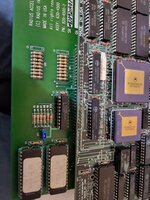
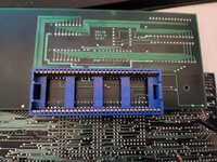
So I finally managed to fix up my Radius 020 accelerator board with new caps and a new diode, however it seems now that installing it in causes it to display a checkerboard screen. Without it it works fine, I have recapped both the AB and the logic board and have seen no issues without it. The main thought I had was the fact I don't have the springs that attach the board with the ROMs on it to ground and maybe 5v? I didn't want to hook them up without knowing where they go for certain, but it looks like one goes to a ground plane and the other seems to have a trace I can't really follow where it goes since it goes under the clip for the CPU.
 

Crutch

Tinkerer
Jul 10, 2022
292
226
43
Chicago
Yeah it for sure won’t work without the springs. I thought they both went to ground but no longer have mine. You could probably just try that …..
 

Kothnaaken

New Tinkerer
Jul 26, 2022
25
3
3
Well, I did what I should have done (but forgot to) and did a little probing with my multimeter before plugging the springs in. They definitely are not both ground, one is though. One goes to pin 16 on the clip which is ground and unsurprisingly that is the one on the ground plane. Now, the other pin has continuity with pin 27 of the cpu socket. Would that connect to 5v on the board? If so where would I be able to find that? The spring naturally seems to want to be near fb1 and r39 on the Plus board there.
 

Kothnaaken

New Tinkerer
Jul 26, 2022
25
3
3
I meant the clip that it clips onto the cpu itself and not the socket, my bad. But here's a couple of pics from the top and bottom, the top left of the bottom facing pic is pin one and I can't really get a good pic of the top of the other side, I feel like the two boards could come apart since there's pins and some sort of holders for said pins between the two boards. However, it's hard to see the traces regardless and the one coming from the one spring I mentioned is visible on the bottom from the corner there, but it goes under the clip there to where you can't see it. Pin one is labelled on the top of the bottom pcb there as well.
 

Attachments

  • 20221228_154911.jpg
    20221228_154911.jpg
    1.6 MB · Views: 43
  • 20221228_154715.jpg
    20221228_154715.jpg
    1.7 MB · Views: 40

Kothnaaken

New Tinkerer
Jul 26, 2022
25
3
3
UPDATE! It does in fact need 5v off the board. I finally got this thing to work. With how much info I gathered myself and from others and from (the very few) other pics I've found maybe I should do a bit of a write up about these since there's virtually no info about them, let alone how to mount them properly. Especially since these all seem to have the same 150uf cap that fails causing the 1N5822 diode to go open circuit. For what it's worth and so anyone needing to know, I got the power from FB1 on the board on the side closest to the edge and ground on one of the ground leads on a resistor on the other.
 
Last edited:
  • Like
Reactions: Patrick