I could use some help getting my Accelerator fixed.
I recently got a Mac Plus with this MicroMac MultiSpeed Accelerator installed. I'm, however, having issues booting from it.
The initial boot screen is fine, but when the logo is supposed to animate off-screen, I get a snowy screen instead, and the system locks up.
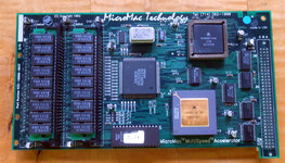
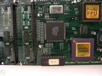
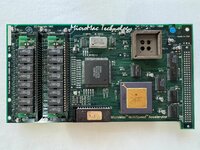
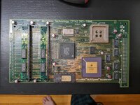
Below are the images of the board from when I first got the system and pulled it out.


Initially, when I received the system, it wouldn't boot at all. Upon close inspection, I noticed the CPU pins were bent on the socket. My guess is that the previous owner tried to do some troubleshooting by pulling the board off and back on, which caused the pin to be bend.


I carefully managed to bend the pins back into place.
I noticed some minor cold joints at the cable connector, so I resoldered those.
I pulled the ROM chip out to verify it was reading well; when I did so, I noticed one of the legs was barely hanging on due to rust, so I burned and put in a new eprom.
This finally takes me to where I'm stuck now.
The system boots with the logo as shown in the video (no bong), then locks up with snow instead of animation. I expect a bong and the MicroMac to animate horizontally off the screen, then the system should bong and continue booting. Here is a clip of the expected behavior.
Here's some of the troubleshooting I did so far.

One interesting thing is that if I replace the 4MB sticks with 1MB sticks, I get a RAM error on boot.

The error reads
The error varies on every boot; "test address" is between 1 and 31, while the "result data" is between 1 and 7B. I initially thought this was probably expected as the jumpers are most likely configured to only accept 4MB sticks, and I can't find any documentation on the jumpers. I recently found this post where the seller states he has 1MB sticks in there, and the jumper settings are the same. So perhaps this clue is meaningful, and there's some error with the RAM (e.g. bad trace?)
Final note, this Mac Plus also came with a working internal hard drive, I see that this system was last working 15 years ago. Seems this issue is what caused the previous owner to sell the system.
I recently got a Mac Plus with this MicroMac MultiSpeed Accelerator installed. I'm, however, having issues booting from it.
The initial boot screen is fine, but when the logo is supposed to animate off-screen, I get a snowy screen instead, and the system locks up.
Below are the images of the board from when I first got the system and pulled it out.
Initially, when I received the system, it wouldn't boot at all. Upon close inspection, I noticed the CPU pins were bent on the socket. My guess is that the previous owner tried to do some troubleshooting by pulling the board off and back on, which caused the pin to be bend.
I carefully managed to bend the pins back into place.
I noticed some minor cold joints at the cable connector, so I resoldered those.
I pulled the ROM chip out to verify it was reading well; when I did so, I noticed one of the legs was barely hanging on due to rust, so I burned and put in a new eprom.
This finally takes me to where I'm stuck now.
The system boots with the logo as shown in the video (no bong), then locks up with snow instead of animation. I expect a bong and the MicroMac to animate horizontally off the screen, then the system should bong and continue booting. Here is a clip of the expected behavior.
Here's some of the troubleshooting I did so far.
- I've tested with a different Mac Plus logic board and get the same issue
- I've reseated the CPU
- I've tested the four 4MB ram sticks in a ram tester and all the stick pass
- I've put in a different set of 4MB RAM sticks and get the same issue
- I've recapped all the electrolytic capacitors, still same issue (there were no signs of any leaks under any capacitors)
- I've cleaned the board and carefully checked for any damaged traces but don't see any
- I've tested with the original ROM eprom chip and get the same issue
One interesting thing is that if I replace the 4MB sticks with 1MB sticks, I get a RAM error on boot.
The error reads
Code:
MEMORY ERROR
TEST ADDRESS  $00000039
TEST DATA     $00000000
RESULT DATA   $0000007B
The error varies on every boot; "test address" is between 1 and 31, while the "result data" is between 1 and 7B. I initially thought this was probably expected as the jumpers are most likely configured to only accept 4MB sticks, and I can't find any documentation on the jumpers. I recently found this post where the seller states he has 1MB sticks in there, and the jumper settings are the same. So perhaps this clue is meaningful, and there's some error with the RAM (e.g. bad trace?)
Final note, this Mac Plus also came with a working internal hard drive, I see that this system was last working 15 years ago. Seems this issue is what caused the previous owner to sell the system.


