Modifications to 128k logic board

wottle

Active Tinkerer
Oct 30, 2021
650
392
63
47
Fort Mill, SC
So, despite my temporary pause on acquiring new machines because of the massive pile of filthy macs in my workshop, what appeared to be a Mac 128k popped up on FB marketplace and I decided to pull the trigger since the price was good.

However, since I don’t think you can actually tell in without opening if it was upgraded to a 512k, it was a bit of a gamble. Just got home with it and it appears to be a 128k logic board (Yay!). However, it doesn’t look like it is a completely original 128k (Boo!). It appears they piggybacked a socket with another 74F253 on top of one of the 74F253 chips labeled AS253 (located at F3), added some resistors and jumped some connections from over by the CPU.
Any idea on what it is and why it was done? Also, any thoughts on if I can reverse it to go back to stock.

Here are some photos:

IMG_7387.jpeg


IMG_7388.jpeg


IMG_7389.jpeg
 

wottle

Active Tinkerer
Oct 30, 2021
650
392
63
47
Fort Mill, SC
OK, I did a little more googling and it looks like this is what was considered a FatMac upgrade? https://ameblo.jp/keroxiee1016/entry-12803881976.html

Fortunately, all the RAM chips appear to be socketed, so I could go back to 128k, is I can get 16 working chips. Given the rarity of stock 128k machines, and the fact I already have 3 512k machines, I think I'd prefer this one to be bone stock, as much as possible. Anyone have any known good RAM chips that would work here?

The other consideration would be installing @Kay K.M.Mods 's FatMac switcher. Id' have to rip out the components here, but at least it would let me switch back to 128k on demand.
 
  • Like
Reactions: JDW

wottle

Active Tinkerer
Oct 30, 2021
650
392
63
47
Fort Mill, SC
After looking over the analog board and the logic board, nothing looked bad so I tried to power it on. Unfortunately, the PSU clicks. I assume like new machines that implied maybe something on the logic board is shorting? I believe I have an analog board recap kit for the 128k/512k.

I think the analog boards are interchangeable, so could I throw the 128k board into the 512k. The floppy won't work because it is an 800k floppy, right? But I can at least see if it boots. Does FloppyEMU work on the 128k externally?
 

Nixontheknight

Tinkerer
Nov 3, 2021
151
25
28
either the logic board's shorted (somewhat unlikely) or the analog board is unable to provide enough current
 

wottle

Active Tinkerer
Oct 30, 2021
650
392
63
47
Fort Mill, SC
either the logic board's shorted (somewhat unlikely) or the analog board is unable to provide enough current
Seems like the logic board is good. Threw it in my 512k and plugged in FloppyEMU and it booted fine. As expected, it is showing 512k memory.

If I undo the mods, will it go back to 128k memory even though the bigger chips have been installed in the sockets for the memory? Or will the larger memory chips cause problems with the memory controller and cause it to not work at all?

I wouldn't mind getting it back to stock, then adding on the FatMac switcher later if I want to be able to toggle between the two.
 
  • Like
Reactions: JDW

JDW

Administrator
Staff member
Founder
Sep 2, 2021
1,747
1,495
113
53
Japan
youtube.com
Hearing the sound would be helpful because there are several. But for now...

Flup sounds have various causes including disconnected cables:

Chirp noises can be a bad CR5:

Low voltage can cause many problems, but that can easily be rectified:

Mostly dead machines:

Also, re-soldering all connectors on the analog board is a must, especially the connector in the upper left corner (when viewed from the component side).
 
  • Like
Reactions: wottle

wottle

Active Tinkerer
Oct 30, 2021
650
392
63
47
Fort Mill, SC
Hearing the sound would be helpful because there are several. But for now...

Flup sounds have various causes including disconnected cables:

Chirp noises can be a bad CR5:

Low voltage can cause many problems, but that can easily be rectified:

Mostly dead machines:

Also, re-soldering all connectors on the analog board is a must, especially the connector in the upper left corner (when viewed from the component side).
It's more of a ticking sound than the flup sound which I had, I think, on a Mac Plus with the fuse in the cable issue that you documented on one of your videos.

I do have the caps for the analog board, which I planned to replace anyway. Just been busy with some other projects, but I'll tackle the recap first, then see if the ticking problem persists, Thanks!
 
  • Like
Reactions: JDW

wottle

Active Tinkerer
Oct 30, 2021
650
392
63
47
Fort Mill, SC
It's more of a ticking sound than the flup sound which I had, I think, on a Mac Plus with the fuse in the cable issue that you documented on one of your videos.

I do have the caps for the analog board, which I planned to replace anyway. Just been busy with some other projects, but I'll tackle the recap first, then see if the ticking problem persists, Thanks!
Unfortunately, the fast ticking persists after the recap of the analog and logic boards. Here’s a video of the ticking sound.


The analog board was remarkably clean and I didn’t see any damaged components. One cap had a little leakage when I pulled it, but no damage to the holes or traces around it. I didn’t also check the cable to make sure the fuse hadn’t blown and it was good. Thoughts?
 

JDW

Administrator
Staff member
Founder
Sep 2, 2021
1,747
1,495
113
53
Japan
youtube.com
Please shoot a photo of the sticker on that flyback so we can see which model it is. I'm curious if it's a very old model.

Next, please wait until it's dark, then turn off all room lights and make sure there are no LEDs or ANYTHING that would produce light. You need a 100% pitch black room. In that condition, you need to keep the machine off but your finger on the power switch. Kill the lights and give your eyes no less than 30 seconds to adjust to the darkness. The longer you wait in the dark, the better. Then focus your eyes on the flyback, then power on the machine. Don't accidentally touch any of the high voltage circuitry! But look very closely to see if you spot any faint blue light. Trust, me, even with adjusted eyes and a pitch black room, it can be hard to spot. But you need to look all around the vicinity of the flyback.

I show that blue light in my video here:


Now with that said, the ticking could be a bad component that isn't able to hold the voltage and flow the current properly. You need to take a magnifying glass and check components on the analog board for cracks or dark spots, especially the big fat diodes. Because if you don't see any blue light in the dark room test, the flyback is probably OK and another component on the board must be the culprit.
 
  • Wow
Reactions: phunguss

wottle

Active Tinkerer
Oct 30, 2021
650
392
63
47
Fort Mill, SC
Please shoot a photo of the sticker on that flyback so we can see which model it is. I'm curious if it's a very old model.

Next, please wait until it's dark, then turn off all room lights and make sure there are no LEDs or ANYTHING that would produce light. You need a 100% pitch black room. In that condition, you need to keep the machine off but your finger on the power switch. Kill the lights and give your eyes no less than 30 seconds to adjust to the darkness. The longer you wait in the dark, the better. Then focus your eyes on the flyback, then power on the machine. Don't accidentally touch any of the high voltage circuitry! But look very closely to see if you spot any faint blue light. Trust, me, even with adjusted eyes and a pitch black room, it can be hard to spot. But you need to look all around the vicinity of the flyback.

I show that blue light in my video here:


Now with that said, the ticking could be a bad component that isn't able to hold the voltage and flow the current properly. You need to take a magnifying glass and check components on the analog board for cracks or dark spots, especially the big fat diodes. Because if you don't see any blue light in the dark room test, the flyback is probably OK and another component on the board must be the culprit.
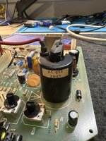
The sticker on the flyback shows “AC-058 ZGCT”.
And I don’t see any cracking, discoloration, or even dirt on the components.

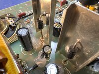
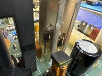
Here are some pictures of the flyback and the diodes I believe you are referring to.

image.jpgimage.jpgimage.jpg

Not sure if it was a valid test of if I was doing it right, but I put my multimeter in diode test mode and tested the diodes pictured. The two in the middle of the board, CR20 and CR21 show voltage (voltage drop?) when measured in both directions. CR21 shows 0.4-0.5V in one direction, and ~ 0.2 in the other. CR20 shows ~0.9 on one direction and 0.2 in the other.

However, CR5 shows no voltage in either direction. Does that indicate it has failed? Can you measure diodes like that while connected to the board, or do I need to remove it?
Any tricks for removal? Do I need to remove the giant metal plate it’s attached to, or can I try to remove it with the plate still on the board?
 

JDW

Administrator
Staff member
Founder
Sep 2, 2021
1,747
1,495
113
53
Japan
youtube.com
As I thought, the oldest Flyback model and one that lacks a bleeder resistor too...

1740192108102.png


That doesn't mean it's bad, but many were swapped out for newer flybacks over time. Sadly, finding replacement flyback is very hard these days because you almost always need to extract them from another Mac!

As to measuring components, you really would need to desolder and measure. Measuring components in-circuit is almost always a bad idea because of how everything is connected together, causing your meter to give you misleading info.

Removing the leg affixed to the metal plate is not necessary, as you could simply remove the foot solder to the PCB, leave it hanging in the air, then do your meter check, then put the foot back and desolder.

Those are the older model diodes though. Newer ones are physically larger and more robust, better handling the current and heat requirements of the board. I have multiple photos on my Flickr account here:


And I created this spreadsheet to show components that have been upgraded over time:


(Note there are 3 "sheets" accessible by tabs at the bottom.)
 
  • Like
Reactions: wottle

wottle

Active Tinkerer
Oct 30, 2021
650
392
63
47
Fort Mill, SC
As I thought, the oldest Flyback model and one that lacks a bleeder resistor too...


That doesn't mean it's bad, but many were swapped out for newer flybacks over time. Sadly, finding replacement flyback is very hard these days because you almost always need to extract them from another Mac!

As to measuring components, you really would need to desolder and measure. Measuring components in-circuit is almost always a bad idea because of how everything is connected together, causing your meter to give you misleading info.

Removing the leg affixed to the metal plate is not necessary, as you could simply remove the foot solder to the PCB, leave it hanging in the air, then do your meter check, then put the foot back and desolder.

Those are the older model diodes though. Newer ones are physically larger and more robust, better handling the current and heat requirements of the board. I have multiple photos on my Flickr account here:


And I created this spreadsheet to show components that have been upgraded over time:


(Note there are 3 "sheets" accessible by tabs at the bottom.)
Yeah, I removed the diode completely figuring it was best for measuring. The diode measurement in one direction now shows 0.4V and 0L in the other. I think that likely the expected result, but I have no EE background and I’m not even sure what a diode does :). However, since I have it off, I may grab a replacement and throw in a new one.

I did take a closer look at the pins on the back side and while the two of the pins on the 4 pin connector looked like they might be developing rings of a cracked solder joint, I don’t believe that was my problem. I did reflow them.
 
  • Like
Reactions: JDW

JDW

Administrator
Staff member
Founder
Sep 2, 2021
1,747
1,495
113
53
Japan
youtube.com
400mV is the Forward Voltage Drop, and that value depends on how much current your meter is running through it, but it sounds like a reasonable value for a good diode. And of course, reading it the reverse way should get you the Overload reading.

I look forward to hearing the result of your darkroom test to see if there is any blue light coming from any leaks in your flyback.
 
Last edited: