3D printed 2.5" HD bracket for CF2IDE

Fizzbinn

Tinkerer
Nov 29, 2021
160
157
43
Charlottesville, VA
I've been using simple, cheap CF2IDE adapters along with industrial Compact Flash cards in my 1400 and 5300 PowerBooks for some time (also looking to do so in a 2300 Duo and "new" 190). I know there are other options with SD cards and what not but I just like this approach.

One aspect that I want to improve on is how they are mounted inside the PowerBooks. I know its fussy, but my current creative use of tape approach grates with my type-A personality, ...even though only I will know what's going on in there.

So not having any 3D modeling skills (or a 3D printer) I started looking for STL models others might have created I could get printed through an online service. I found several possibilities but also discovered a couple complicating issues.


Issue #1 - There are actually two versions of these adapters that look VERY similar but have different "mounting" points and 44-pin IDE connector types!

Version B1: "CF-IDE44/2.0mm ADAPTER V.B1" (left/top below)
Version H2: "CF-IDE44/2.0mm ADAPTER V.H2" (right/bottom below)

IMG_4142.jpeg


IMG_4143.jpeg


IMG_4144.jpeg


The two oldest ones I have are version B1, ones I purchased last fall are version H2. It seems like Amazon and eBay only have H2 available now. Compared to B1, H2 has two additional notches on the sides, a relocated master/slave jumper (and through hole lead protrusions) as well as an IDE connection that sandwiches the board vs. being an L shaped one on the top side of the board. I'm guessing the H2 version is cheaper to make.

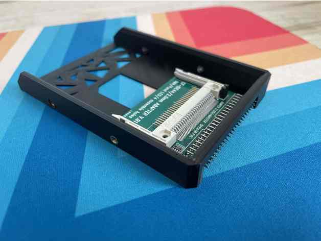
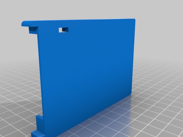
Ideally a 3D printed 2.5" HD adapter bracket would position the IDE connection in the same location relative to the hard disk mounting screw holes:

IMG_4130.jpeg


IMG_4132.jpeg


IMG_4133 (1).jpeg


Which leads us to...


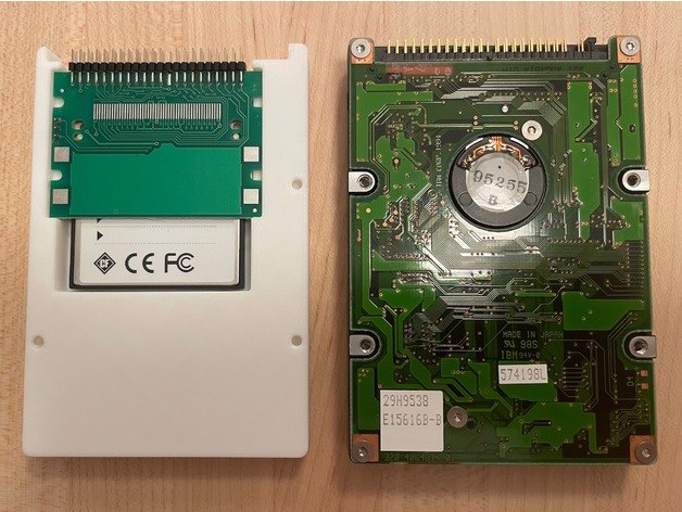
Issue #2 - Sometime in 1997(ish) the hard disk mounting screw hole positions changed for 2.5" HDs!

In the older drives the screw hole positions are toward the middle of the drive, while for later drives (up to today) they are towards the corners. It appears this change happened during the production of the PB1400:

Old Style: PB 1400c/133c 1.3GB HD and Apple bracket (left/top below)
Modern Style: PB 1400c/166c 2.0GB HD and Apple bracket (right/bottom below)


IMG_4135.jpeg


IMG_4137.jpeg


IMG_4138 (1).jpeg


To be continued...
 
Last edited:
  • Wow
Reactions: retr01

Fizzbinn

Tinkerer
Nov 29, 2021
160
157
43
Charlottesville, VA
So here are the CF2IDE 2.5" HD bracket/adapter/holder STL models I found:

1) "COMPACTFLASH READER ADAPTER TO STD IDE HDD SIZE"
https://cults3d.com/en/3d-model/gadget/compactflash-reader-adapter-to-std-ide-hdd-size
1683916010569.png

Comment: Modeled for the "B1" CF2IDE adapter and using the modern screw hole positions, but only on sides, not bottom. No go for PB1400 and older which require old style screw hole positions on the bottom.


2) "Libretto 50CT / 70CT CompactFlash holder"
1683916250072.png

Comment: Modeled for the "H2" CF2IDE adapter, and using the the old screw hole positions, but only on sides, not bottom. No go for PB1400 and older which require screw hole positions on the bottom. Also the feature of being able to store two other CF cards seems of no real use and blocks the ability to remove CF cards without removing the CF2IDE adapter too. In my thinking the CF2IDE adapter would be best affixed to the bracket via screws/glue.

3) "CF-to-IDE V.H2 Holder"
1683916638249.png

Comment: Modeled for the "H2" CF2IDE adapter, and using the modern screw hole positions, but only on sides, not bottom. No go for PB1400 and older which require old style screw hole positions on the bottom. I DO like the minimalist nature of this one though, reminds me of the BlueSCSI brackets (which do use the old style screw hole positions and have them on the sides and bottom...)

4) "CF2IDE 2.5" HDD Enclosure"
1683917460940.png

Comment: Modeled for the "B1" CF2IDE adapter, and using the the old screw hole positions, but only on sides, not bottom. No go for PB1400 and older which require screw hole positions on the bottom.


I left contemplating several options:

A) Maybe this is motivation to learn how to edit/create 3D models, how hard could it be to learn starting from my MacPaint level graphics skills! 😬
B) Is there anyone else with these skills interested enough to take it on? 🥺
C) Maybe I should just buy prints of #4 and drill new bottom mount holes and exacto blade cut out a knotch for the master/slave through hole lead protrusions to accommodate "2" CF2IDE adapters. 🤪
 
Last edited:
  • Like
Reactions: Kai Robinson

Fizzbinn

Tinkerer
Nov 29, 2021
160
157
43
Charlottesville, VA
So here are the CF2IDE 2.5" HD bracket/adapter/holder STL models I found:

1) "COMPACTFLASH READER ADAPTER TO STD IDE HDD SIZE"
https://cults3d.com/en/3d-model/gadget/compactflash-reader-adapter-to-std-ide-hdd-size
View attachment 12263
Comment: Modeled for the "B1" CF2IDE adapter and using the modern screw hole positions, but only on sides, not bottom. No go for PB1400 and older which require old style screw hole positions on the bottom.


2) "Libretto 50CT / 70CT CompactFlash holder"
View attachment 12264
Comment: Modeled for the "H2" CF2IDE adapter, and using the the old screw hole positions, but only on sides, not bottom. No go for PB1400 and older which require screw hole positions on the bottom. Also the feature of being able to store two other CF cards seems of no real use and blocks the ability to remove CF cards without removing the CF2IDE adapter too. In my thinking the CF2IDE adapter would be best affixed to the bracket via screws/glue.

3) "CF-to-IDE V.H2 Holder"
View attachment 12265
Comment: Modeled for the "H2" CF2IDE adapter, and using the modern screw hole positions, but only on sides, not bottom. No go for PB1400 and older which require old style screw hole positions on the bottom. I DO like the minimalist nature of this one though, reminds me of the BlueSCSI brackets (which do use the old style screw hole positions and have them on the sides and bottom...)

4) "CF2IDE 2.5" HDD Enclosure"
View attachment 12266
Comment: Modeled for the "B1" CF2IDE adapter, and using the the old screw hole positions, but only on sides, not bottom. No go for PB1400 and older which require screw hole positions on the bottom.


I left contemplating several options:

A) Maybe this is motivation to learn how to edit/create 3D models, how hard could it be to learn starting from my MacPaint level graphics skills! 😬
B) Is there anyone else with these skills interested enough to take it on? 🥺
C) Maybe I should just buy prints of #4 and drill new bottom mount holes and exacto blade cut out a knotch for the master/slave through hole lead protrusions to accommodate "2" CF2IDE adapters. 🤪

I recently picked back up on this, sparked in no small part by getting a 3D printer for Christmas (a Bambu Labs A1 mini). This lead me to go with option A and learn some 3D modeling, starting with how to tweak existing models somewhat using FreeCAD and YouTube tutorials.

I decided to modify this model:

"Compact Flash adapter adapter"

Which had what I was looking for, modeled for the H2 CF2IDE adapter and old style screw hole positions, with the exception that it doesn't have bottom screw hole positions just the side ones.

I'm not sure exactly what I was expecting but "just putting some new holes in something" turned out to be a good learning experience, strangely both easy and hard in different ways.

The results:

IMG_4976.jpeg


IMG_4978.jpeg


IMG_4979.jpeg


An original PowerBook 1400 HD in its mounting bracket (screws removed):
IMG_4983.jpeg


The new 3D printed adapter in the same PowerBook 1400 HD mounting bracket:
IMG_4980.jpeg


I was actually only able to get three of the bottom screw positions in the model as the forth is blocked by the CF2IDE adapter board. The board needs to be in the position it is in order to align the IDE pins with where a real HD has them.

The STL file is available here:
 
Last edited:
  • Like
Reactions: S. Pupp and eric