Hi everyone! A few years ago I got a Color Classic that didn't work properly (can't recall the exact symptoms at that point - again, it has been a while...). So I performed the obvious operations: Recapping the logic board with Tantalum capacitors and the more "error prone" caps from the analog board as lined out by @Branchus. At that point I got the CC to boot up to the boot-media-question-mark (original HDD tested & declared dead, no replacement yet). However, the machine didn't seem to make any attempts at reading a floppy when inserted. The question mark kept flashing, the cursor did move but no noise whatsoever from the floppy drive (already did a service on that, tested it and works). Also in some cases, nothing happened at all, no life after switching on power and pressing the boot button from the keyboard (tried different keyboards, all work on other machines). That is where I left the project some time ago.
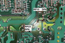
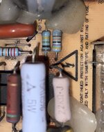
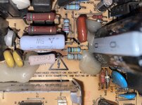
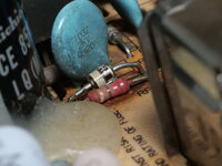
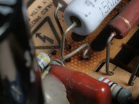
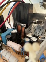
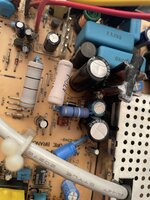
A week ago or so I stumbled upon the component upgrade video by @JDW and the tip for using an even cooler running diode. Inspecting the diodes on my CC's AB showed the same discoloration on the board, so I replaced the two diodes DL21/22 with a DOI-201 packaged 1N5355B + a copper heatsink (looks a bit weird, I admit, but should get the job done. The two copper plates are held together at the top so that they don't vibrate using a bit of heat shrink that is additionally hardened with a bit of super glue), RL22, RL62, RF11, DF2 and the surrounding electrolytic capacitors that haven't been replaced yet (just in case they were affected by the heat - I know, not really necessary, but if I am already working on that area...).
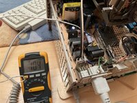
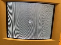
Unfortunately this is not enough: There is a picture (although with a strong blue tint that doesn't really come across on the video I uploaded and a bit of a geometric distortion at the top and bottom, though I suspect that is more of an adjustment issue) and the CC tries to boot but shuts down/looses power after less than a minute (see video). Sometimes it gets to the boot-media-question-mark, but not always. Putting in a floppy doesn't seem to make a difference, no audible attempt at trying to read anything from that. With a bit of help from my dad we were able to read the voltages on the HDD power connector (as there isn't a disk in there) in the short time it powers on but nothing out of the ordinary there either (just shy of 12V and 5V).
This is where I'm currently stuck and need help/advice on what to take a look at next. I still suspect that the analog board is the (main) culprit here as the CC gets to the point where I can see and move the cursor, so I don't think its the logic board (also, the blue tint of the image) - on the other hand, the floppy drive showing no signs of life could either be a power issue there or a failure of the floppy controller on the LB? But then, why would this cause the machine to suddenly lose power? Any help or advice is greatly appreciated! Please feel free to ask me for any additional information required to troubleshoot this in case I missed something!
A week ago or so I stumbled upon the component upgrade video by @JDW and the tip for using an even cooler running diode. Inspecting the diodes on my CC's AB showed the same discoloration on the board, so I replaced the two diodes DL21/22 with a DOI-201 packaged 1N5355B + a copper heatsink (looks a bit weird, I admit, but should get the job done. The two copper plates are held together at the top so that they don't vibrate using a bit of heat shrink that is additionally hardened with a bit of super glue), RL22, RL62, RF11, DF2 and the surrounding electrolytic capacitors that haven't been replaced yet (just in case they were affected by the heat - I know, not really necessary, but if I am already working on that area...).
Unfortunately this is not enough: There is a picture (although with a strong blue tint that doesn't really come across on the video I uploaded and a bit of a geometric distortion at the top and bottom, though I suspect that is more of an adjustment issue) and the CC tries to boot but shuts down/looses power after less than a minute (see video). Sometimes it gets to the boot-media-question-mark, but not always. Putting in a floppy doesn't seem to make a difference, no audible attempt at trying to read anything from that. With a bit of help from my dad we were able to read the voltages on the HDD power connector (as there isn't a disk in there) in the short time it powers on but nothing out of the ordinary there either (just shy of 12V and 5V).
This is where I'm currently stuck and need help/advice on what to take a look at next. I still suspect that the analog board is the (main) culprit here as the CC gets to the point where I can see and move the cursor, so I don't think its the logic board (also, the blue tint of the image) - on the other hand, the floppy drive showing no signs of life could either be a power issue there or a failure of the floppy controller on the LB? But then, why would this cause the machine to suddenly lose power? Any help or advice is greatly appreciated! Please feel free to ask me for any additional information required to troubleshoot this in case I missed something!

") I don't think people will solder a deal short across their Zener, but you never know what people will do at times.
I don't think people will solder a deal short across their Zener, but you never know what people will do at times.