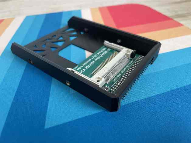
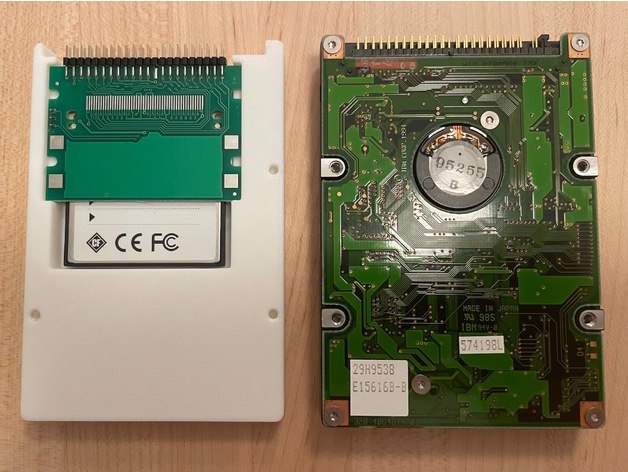
I've been using simple, cheap CF2IDE adapters along with industrial Compact Flash cards in my 1400 and 5300 PowerBooks for some time (also looking to do so in a 2300 Duo and "new" 190). I know there are other options with SD cards and what not but I just like this approach.
One aspect that I want to improve on is how they are mounted inside the PowerBooks. I know its fussy, but my current creative use of tape approach grates with my type-A personality, ...even though only I will know what's going on in there.
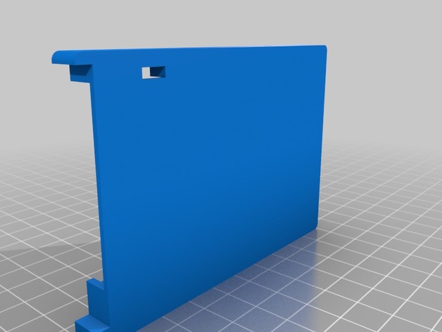
So not having any 3D modeling skills (or a 3D printer) I started looking for STL models others might have created I could get printed through an online service. I found several possibilities but also discovered a couple complicating issues.
Issue #1 - There are actually two versions of these adapters that look VERY similar but have different "mounting" points and 44-pin IDE connector types!
Version B1: "CF-IDE44/2.0mm ADAPTER V.B1" (left/top below)
Version H2: "CF-IDE44/2.0mm ADAPTER V.H2" (right/bottom below)


The two oldest ones I have are version B1, ones I purchased last fall are version H2. It seems like Amazon and eBay only have H2 available now. Compared to B1, H2 has two additional notches on the sides, a relocated master/slave jumper (and through hole lead protrusions) as well as an IDE connection that sandwiches the board vs. being an L shaped one on the top side of the board. I'm guessing the H2 version is cheaper to make.
Ideally a 3D printed 2.5" HD adapter bracket would position the IDE connection in the same location relative to the hard disk mounting screw holes:


Which leads us to...
Issue #2 - Sometime in 1997(ish) the hard disk mounting screw hole positions changed for 2.5" HDs!
In the older drives the screw hole positions are toward the middle of the drive, while for later drives (up to today) they are towards the corners. It appears this change happened during the production of the PB1400:
Old Style: PB 1400c/133c 1.3GB HD and Apple bracket (left/top below)
Modern Style: PB 1400c/166c 2.0GB HD and Apple bracket (right/bottom below)


To be continued...
One aspect that I want to improve on is how they are mounted inside the PowerBooks. I know its fussy, but my current creative use of tape approach grates with my type-A personality, ...even though only I will know what's going on in there.
So not having any 3D modeling skills (or a 3D printer) I started looking for STL models others might have created I could get printed through an online service. I found several possibilities but also discovered a couple complicating issues.
Issue #1 - There are actually two versions of these adapters that look VERY similar but have different "mounting" points and 44-pin IDE connector types!
Version B1: "CF-IDE44/2.0mm ADAPTER V.B1" (left/top below)
Version H2: "CF-IDE44/2.0mm ADAPTER V.H2" (right/bottom below)
The two oldest ones I have are version B1, ones I purchased last fall are version H2. It seems like Amazon and eBay only have H2 available now. Compared to B1, H2 has two additional notches on the sides, a relocated master/slave jumper (and through hole lead protrusions) as well as an IDE connection that sandwiches the board vs. being an L shaped one on the top side of the board. I'm guessing the H2 version is cheaper to make.
Ideally a 3D printed 2.5" HD adapter bracket would position the IDE connection in the same location relative to the hard disk mounting screw holes:
Which leads us to...
Issue #2 - Sometime in 1997(ish) the hard disk mounting screw hole positions changed for 2.5" HDs!
In the older drives the screw hole positions are toward the middle of the drive, while for later drives (up to today) they are towards the corners. It appears this change happened during the production of the PB1400:
Old Style: PB 1400c/133c 1.3GB HD and Apple bracket (left/top below)
Modern Style: PB 1400c/166c 2.0GB HD and Apple bracket (right/bottom below)
To be continued...
Last edited:


