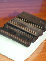
68000 CPU interface replacement for Killy Klip - Photos of alternatives wanted

Trash80toG4

Active Tinkerer
Apr 1, 2022
910
260
63
Bermuda Triangle, NC USA
We need a reliable replacement for new build accelerators (e.g. my long running MicroMac Performer Redux project)

I'm lucky enough to have a pair of Killy Klips for my SE/Plus/Classic Performer, but new version will be for SE and Plus only with passthru for Radius FPD/TPD cards as well as a connector to bring the full 68000 "PDS" above board in front of the MagicBus interface for future development projects.

'nuf said there, here's an example I found, anything and everything out there that can be printed and built would be what I'm looking for as reference designs:

KillyKlip-and-Such-00.JPG


For new build accelerators the contact interface with the PCB need not align with the 68000's legs, only the contacts themselves, so spacing of the thruholes for the Killy Klip replacement on accelerators and expansion cards is fluid.

I have a couple of others, but need find them and post them along with trolling suggestions. Nice community project maybe? :)
 
Last edited:

Trash80toG4

Active Tinkerer
Apr 1, 2022
910
260
63
Bermuda Triangle, NC USA
Been a bit, but just ransacked my MLA pics archive. This is what needs replacing with something more workable for the 10cm Square PCB era/card development era.

post-902-0-02591700-1482981749.jpg


post-902-0-35983700-1482981772.jpg


That was a wonderful, fairly mass produced kluge at the time, but not doable in a short run in this day and age. Besides, it was a bit wonky back when and we certainly don't need that now.

Design will be useful across any number of DIP IC adapters for experimentation if a chip select or power cutout is implemented on the original IC.
 

Trash80toG4

Active Tinkerer
Apr 1, 2022
910
260
63
Bermuda Triangle, NC USA
Might that be the one mentioned in a thread over at the MLA? ISTR the designer saying it was a one use kinda deal at the time. I posted that first pic over where that was mentioned.

Like I said, nice community project?
 

Trash80toG4

Active Tinkerer
Apr 1, 2022
910
260
63
Bermuda Triangle, NC USA
Thanks, that's what brought my notions back closer to the fire. :)

cloneyclip_beautyshot.jpg


Took one glance again and now am wondering how flexible the thinnest single sided PCB might be if cut in a comb pattern dividing pads for flex-contact up along IC legs with RA Headers installed in the thruholes pointing straight up?

IOW, split your board in halves to sock the teeth of the comb upside the IC legs with header pins (or sockets?) pointing straight up? The inter-leg support structure of the orange beauty above will come in handy for corralling such a bodge?

Had snagged these pics for a budding Interesting Parts Catalog thread.

Straight-RA-Machine-PCB Pins.JPG


Pic illustrates the concept well enough I think?

moar goodies:

.050 solder Cup-Headers-sockets.JPG
 
Last edited:

Stephen

BetterBit
Staff member
Founder
Sep 5, 2021
204
250
63
San Francisco
I was lucky and could submit a few prototypes to JLC before they enforced minimum PCB size guidelines. I used the thinnest board and made "tongs" that came down to touch the sides of the legs, held in place with a 3D printed frame. My results weren't promising but perhaps there is a better technique.
 

twensel76

New Tinkerer
Jul 27, 2024
2
0
1
I was lucky and could submit a few prototypes to JLC before they enforced minimum PCB size guidelines. I used the thinnest board and made "tongs" that came down to touch the sides of the legs, held in place with a 3D printed frame. My results weren't promising but perhaps there is a better technique.
Can you provide any data? I need to replicate and print. Thank you.