Hello together.
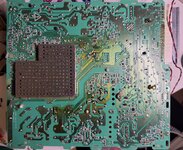
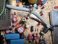
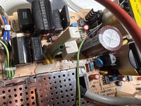
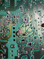
Mainly motivated by JDW’s excellent videos on YouTube, I decided to do the 84V VGA mod on my Color Classic too. To accomplish that, I cut the trace between pin 8 and pin 9, protected the copper with silicone (as i don’t have solder mask) and then connected pin 8 and pin 10 using a thick 1mm2 wire. Then I moved the 0 ohms resistor from J78 to J79. I ensured that nothing is shorted by taking measurements with my multimeter and compared the resistance of pin 8 and pin 10 with that of pin 8 to pin 9. I measured 0.05 Ohms vs. 0.25 Ohms.
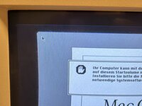
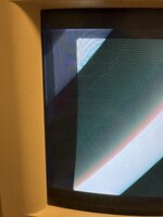
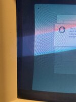
After powering it on with the stock logic board installed, I noticed a wide light gray (lit) border followed by a dark border. Also the picture is a little bit distorted as noticeable in the second and third picture.
It’s also noticeable that the light gray border moves up and down as well when turning the vertical trimmer on the back on the device. Also it’s wider on the upper side than on the lower side. If I turn the horizontal trimmer, the screen content of the OS moves from left to right but no changes in the bars. Is the cutoff set too high or is this another issue? I know that doing the VGA mod involves readjusting the tube but I want to ensure if this is really only an adjustment related issue.
Also I’m noticing a humming/whistling noise coming from the tube which was not there before i performed the mod.
The next step will be doing the beefy components upgrade next week and putting in a LC575 logic board once it arrives from Japan.
Mainly motivated by JDW’s excellent videos on YouTube, I decided to do the 84V VGA mod on my Color Classic too. To accomplish that, I cut the trace between pin 8 and pin 9, protected the copper with silicone (as i don’t have solder mask) and then connected pin 8 and pin 10 using a thick 1mm2 wire. Then I moved the 0 ohms resistor from J78 to J79. I ensured that nothing is shorted by taking measurements with my multimeter and compared the resistance of pin 8 and pin 10 with that of pin 8 to pin 9. I measured 0.05 Ohms vs. 0.25 Ohms.
After powering it on with the stock logic board installed, I noticed a wide light gray (lit) border followed by a dark border. Also the picture is a little bit distorted as noticeable in the second and third picture.
It’s also noticeable that the light gray border moves up and down as well when turning the vertical trimmer on the back on the device. Also it’s wider on the upper side than on the lower side. If I turn the horizontal trimmer, the screen content of the OS moves from left to right but no changes in the bars. Is the cutoff set too high or is this another issue? I know that doing the VGA mod involves readjusting the tube but I want to ensure if this is really only an adjustment related issue.
Also I’m noticing a humming/whistling noise coming from the tube which was not there before i performed the mod.
The next step will be doing the beefy components upgrade next week and putting in a LC575 logic board once it arrives from Japan.
Attachments
Last edited: