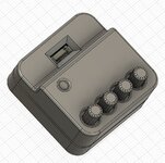
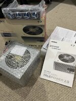
The Antec TP-II 550 is a powerful power supply that was originally offered in two variants: one with the TrueControl panel and one without. The TrueControl panel was a unique feature that mounted in a 5.25" drive bay and provided manual voltage adjustment through four potentiometers (pots) for the 12V, 5V, 3.3V, and fan voltage rails.
If you have the Truecontrol 2.0 version without the control panel—or if you've lost the original panel—you may have noticed a significant problem: the power supply defaults to voltages that are barely within ATX specification, with all rails running quite low. This makes the PSU difficult to use reliably without the control panel.
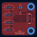
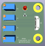
Fortunately, with some community help and reverse engineering, it's possible to build a simple replacement control circuit that restores full functionality to this beast of a power supply. This guide will walk you through creating your own TrueControl replacement using readily available components.
Credits
This project was made possible thanks to the collaborative efforts of several community members:
General Recapping Notes:
Connector:
Optional:
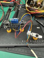
Step 1: Prepare the Potentiometers
For each of the four potentiometers:
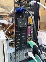
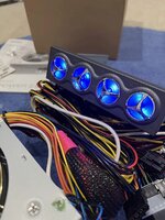
For a temporary solution, I've hot glued the assembly directly to the power supply casing. I may do a PCB in the future, but for now... this'll do
While this may not be as elegant as the original TrueControl panel, it's a functional and cost-effective way to restore your Antec TP-II 550 w/ Truecontrol to full working order. The total cost in components is minimal, and the assembly is straightforward enough for anyone comfortable with basic soldering.
Happy building, and enjoy your newly functional power supply!
If you have the Truecontrol 2.0 version without the control panel—or if you've lost the original panel—you may have noticed a significant problem: the power supply defaults to voltages that are barely within ATX specification, with all rails running quite low. This makes the PSU difficult to use reliably without the control panel.
Fortunately, with some community help and reverse engineering, it's possible to build a simple replacement control circuit that restores full functionality to this beast of a power supply. This guide will walk you through creating your own TrueControl replacement using readily available components.
Credits
This project was made possible thanks to the collaborative efforts of several community members:
- @zigzagjoe and @mmu_man - Identified the connector type used by the TrueControl panel
- Mr. Cacodemon (Power Supply Central Discord) - Provided PCB photos, pinouts, and pot measurements from an actual control panel and the caps list
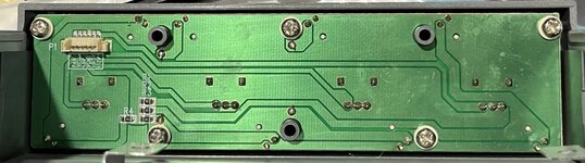
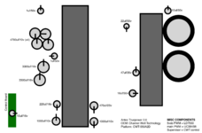
Recapping
Before you Begin, these are almost guaranteed to need to be recapped, below is the list of caps you'll need, I've created a Digikey list as well, but it's missing the fan daughterboard cap that's usually just fine: https://www.digikey.com/en/mylists/list/2HG381A1MPGeneral Recapping Notes:
- Original brands used will vary but will always be the same spec. For example the 22uf 50v is a Fuhjyyu TN instead of Koshin KRM or the 4700uf 10v are Teapo SC instead of Fuhjyyu TM
- The list only applies to the non EU models, EU models with APFC use a different platform from CWT that is the same other then the primary side which has APFC circuitry. so many of the smaller value caps will likely be different or placed in different spots.
- See the recapping map attached to this post if you need it! This map is the same for all non-EU Truepower 2.0 Models
| Caps (Orig -> Recommended Replacement) | Notes | Qty |
| 4700uf 10v Fuhjyyu TM -> 4700uf 6.3v rubycon ZLQ | 10mm diameter | 4 |
| 3300uf 16v Fuhjyyu TM -> 3300uf 16v elite ED | These generally don't go bad, but the Elite brand caps are hard to find, I have two alternatives in the digikey list for these depending on what's in stock. One of them is 12.5mm (panasonic FM) diameter though so they'll be a tight fit but still work. Originals were 10mm, which the Elite ED are, but are hard to find in stock anywhere. | 2 |
| 1000uf 10v Fuhjyyu TN -> 1000uf 10v rubycon ZLH | 2 | |
| 470uf 25v Fuhjyyu TN -> 470uf 25v rubycon ZLH | 1 | |
| 220uf 16v Koshin KRM -> 220uf 16v rubycon YXJ | 1 | |
| 47uf 35v Fuhjyyu TN -> 47uf 35v rubycon YXM | Chemicon LE is the equivalent if the YXM isn't in stock, (any general purpose cap will do the same) | 1 |
| 22uf 50v Koshin KRM -> 22uf 50v rubycon YXM | Chemicon LE is the equivalent if the YXM isn't in stock, (any general purpose cap will do the same) | 1 |
| 10uf 50v Fuhjyyu TN -> 10uf 50v rubycon YXM | Chemicon LE is the equivalent if the YXM isn't in stock, (any general purpose cap will do the same) | 2 |
| 10uf 16v koshin KRJ -> 10uf 16v kemet ESS | Fan daughterboard, 4x7mm | 1 |
| 1uf 50v Fuhjyyu TN -> 1uf 50v rubycon YXM | Chemicon LE is the equivalent if the YXM isn't in stock, (any general purpose cap will do the same) | 2 |
What You'll Need
Potentiometers (1/2 watt or 1/4 watt):- 12V rail: 4-600Ω pot (1kΩ pot works well)
- 3.3V rail: 4-1500Ω pot (2kΩ pot works well)
- 5V rail: 4-1500Ω pot (2kΩ pot works well)
- Fan line: 5400-5600Ω pot (5kΩ pot works well)
- Example pots on Amazon
Connector:
- Molex PicoBlade connector (available from DigiKey or Amazon)
- Amazon bundle option
Optional:
- 330Ω SMD resistors for LEDs (if you want indicator lights)
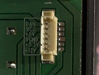
TrueControl Pinout
| Wire Color | Function |
| Yellow | 12V |
| Brown | 3.3V |
| Black | Ground (Vgnd) |
| Red | 5V |
| Green | Vcc (LED power only) |
| Blue | Fan |
Assembly Instructions
Step 1: Prepare the Potentiometers
For each of the four potentiometers:
- Identify pins 1, 2, and 3 on the pot
- Connect pins 1 and 2 together—these will be your common ground connection
- Pin 3 will be your voltage adjustment output
- Connect the joined pins 1 & 2 from all four pots to the Black (Ground) wire on the connector
- Connect pin 3 of each pot to its corresponding wire:
- 12V pot → Yellow wire
- 3.3V pot → Brown wire
- 5V pot → Red wire
- Fan pot → Blue wire
- The Green (Vcc) wire is only needed if you're adding LED indicators
- Connect your assembled control circuit to the power supply connector
- Use your BIOS readings or a multimeter to check voltages
- Adjust each potentiometer until voltages and fan are set to preference:
- Voltages: The 5v, 3.3v, and 12v knobs allows individual adjustment of voltages even while the system is running, without interrupting system functions. With this functionality you can stabilize a heavily loaded system, even when overclocking.
(Note: you can only adjust within ATX spec (±5%) (the psu will keep within ±1-3% of set voltages). The PSU has UVP (under voltage protection) and OVP (over voltage protection), so even if you do somehow go out of allowed range it'll shut off. - Fan: The fan knob allows adjustment of minimum speed of internal PSU fan as well as case fans connected to Fan Only connectors.
(Note: this adjusts the fan speed to temp curve, this is why adjusting the knob will appear to not do much when the psu is cool)
- Voltages: The 5v, 3.3v, and 12v knobs allows individual adjustment of voltages even while the system is running, without interrupting system functions. With this functionality you can stabilize a heavily loaded system, even when overclocking.
For a temporary solution, I've hot glued the assembly directly to the power supply casing. I may do a PCB in the future, but for now... this'll do
While this may not be as elegant as the original TrueControl panel, it's a functional and cost-effective way to restore your Antec TP-II 550 w/ Truecontrol to full working order. The total cost in components is minimal, and the assembly is straightforward enough for anyone comfortable with basic soldering.
Happy building, and enjoy your newly functional power supply!
General Notes on the TruePower Line:
The Antec truepower 2.0 line was a high end set of models from Antec released in 2005 to replace the original truepower line. The truepower 2.0 had 4 different versions:- Standard models available in 4 wattages, TPII-380, TPII-430, TPII-480, TPII-550 (APFC EU models, TPII-380P, TPII-430P, TPII-480P, TPII-550P)
- EPS12V model for server use TP2-550EPS12V (APFC EU model, TP2-550PEPS12V) (only 2.0 model with dual fans like the original truepower models)
- TRUE Blue 2.0 model, TPII-480 Blue (APFC EU model, TPII-480P Blue) same as standard 480w model but with clear fan and blue LEDs
- TRUE Control 2.0 model, TPII-550 Control (APFC EU model, TPII-550P Control) TRUEII-550 with 5.25 bay control panel for fine voltage adjustment for overclocking and fan speed override control.
Attachments
Last edited: