Apple Cinema Display HD 23" (DVI) repair - voltage problem

fehervaria

Tinkerer
Sep 23, 2021
153
158
43
47
North Germany
I purchased for postage an aluminum Cinema Display 23" with the DVI / USB / FW / Power connectors cable a few months ago. It was marked as repaired, but after few minutes of usage it was flickering a little and then went black - power off the LCD. That time I had no time, but I read after and find out the "typical" failure is the voltage regulator wrong voltage output. (LD1117ADT33TR) It should give 3.3V. After opening the housing of it, a big mess was welcomed. Someone was "already there" and bypassed the original malfunctioning voltage regulator with some bondage wires and "on the fly" voltage regulator! And it was not working either.
I find this video:

I followed the measurements: finally I was able to repair the voltage regulator with the original component (LD1117ADT33TR). It was working again few hours.
I switched off to move back to its housing but I had a feeling "try it again after cool down"...
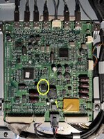
When I applied the power, I caught the magic smoke from the board, and I've seen a glowing component. (marked with red arrow)
Could you please tell me what is that exact component marked with the "What is this?" red arrow? I also marked with an oval the voltage regulator.
IMG_5985.jpeg
 

Attachments

  • IMG_5983.jpeg
    IMG_5983.jpeg
    2.6 MB · Views: 76

fehervaria

Tinkerer
Sep 23, 2021
153
158
43
47
North Germany
I was able to do "better" photo about the damaged component:
IMG_5986.jpeg
IMG_5987.jpeg

What could be this?
Does any of you knows it?

I removed it from the board and checked the pads:
the bottom right is the power, 24.5V, connected directly to the fuse's pin,
the top pin/pad is GND,
the bottom left is connected to the C12 negative pin...

Where can I fine equivalent exchange component?
 

Kai Robinson

TinkerDifferent Board President 2023
Staff member
Founder
Sep 2, 2021
1,032
1
1,065
113
41
Worthing, UK

fehervaria

Tinkerer
Sep 23, 2021
153
158
43
47
North Germany
@Kai Robinson
Finally, the BSR16 arrived. Soldering was 5 minutes, trying: magic smoke... :-(
Based on the datasheet from Mouser, the pin2 (bottom right) is the emitter, but it gets 24.5V... it should get 5V. What am I missing? Is it possible the original component has mirrored pinout? from collector side (bottom left pin) is ok for max. 60V...
 

Cashed

New Tinkerer
Jul 10, 2022
3
6
3
Could you provide a closer photo of the voltage regulator, also from underneath -the other side of the board.
Also a photo of the voltage regulator you replaced.
 
Last edited:
  • Like
Reactions: fehervaria

fehervaria

Tinkerer
Sep 23, 2021
153
158
43
47
North Germany
Could you provide a closer photo of the voltage regulator, also from underneath -the other side of the board.
Also a photo of the voltage regulator you replaced.
Sorry for the late reply.
My problem is "before" the voltage regulator. This is directly after the big yellow fuse. (You can see in the original post's photos) The BSR16 is the 2nd component after the power input.
The original voltage regulator is an LD1117ADT33TR and I have exactly the same for replacement.
IMG_6060.jpeg
 
  • Like
Reactions: Cashed

Cashed

New Tinkerer
Jul 10, 2022
3
6
3
Great, thanks -I see it's the same.
Yeah I know the issue occurs before the volt reg, just wanted two flies with one swat.
As to why I asked for a photo from the other side of the board; My thought was -maybe excess of solder tin, after shorting/during applying.
(pic# 2 from Aug 1)
I know it's a pain to disassemble, but have you had a peek on the other side?