All,
I managed to de-repair the internal power converter. There are two possible issues, at least. As I had the computer open, I decided to replace the capacitors, as a precaution. I did replace the capacitors in two batches (due to some missing cap's) . On the first run I noticed that one capacitor, C2, is installed wrong way, as opposite what the silk screen says. Also there was and is a short piece of wire connecting two vias underside and a trace seems to be cut. The converter did work before i replaced the first batch, including this C2, and it also worked after replaces. So I guess the silk screen is erratic.
I did not notice any other capacitor to be installed wrong way related to the silk screen, but I can't be certain.
After the rest of the capacitors arrived I replaced those too. Then I did put the board back in the casing and tried to get the latch (?) to hold the transistor against the casing correctly in place. But I guess I failed with that, as the converter does not produce any voltage outwards anymore. I checked the transistor (C3568), and it seems to be shorted. This may have caused some other damage too.
Now the questions are
* does anybody have schematics of this converter? Details are below.
* could somebody confirm that C2 is only capacitor to be installed wrong way and the trace beneath is cut
* what voltages should be seen on pins of the transistor?
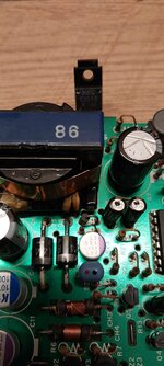
On the board itself is text PCU-266E. On the metal casing are texts TDK 699-0230, CE-045 8511 and serial number.
And yes, I managed to pull one of the pads of C2, but corrected it with a bit of solder bridge.
Please see pictures below. Unfortunately the trace cut is just below the red arrow, but somehow visible.


I managed to de-repair the internal power converter. There are two possible issues, at least. As I had the computer open, I decided to replace the capacitors, as a precaution. I did replace the capacitors in two batches (due to some missing cap's) . On the first run I noticed that one capacitor, C2, is installed wrong way, as opposite what the silk screen says. Also there was and is a short piece of wire connecting two vias underside and a trace seems to be cut. The converter did work before i replaced the first batch, including this C2, and it also worked after replaces. So I guess the silk screen is erratic.
I did not notice any other capacitor to be installed wrong way related to the silk screen, but I can't be certain.
After the rest of the capacitors arrived I replaced those too. Then I did put the board back in the casing and tried to get the latch (?) to hold the transistor against the casing correctly in place. But I guess I failed with that, as the converter does not produce any voltage outwards anymore. I checked the transistor (C3568), and it seems to be shorted. This may have caused some other damage too.
Now the questions are
* does anybody have schematics of this converter? Details are below.
* could somebody confirm that C2 is only capacitor to be installed wrong way and the trace beneath is cut
* what voltages should be seen on pins of the transistor?
On the board itself is text PCU-266E. On the metal casing are texts TDK 699-0230, CE-045 8511 and serial number.
And yes, I managed to pull one of the pads of C2, but corrected it with a bit of solder bridge.
Please see pictures below. Unfortunately the trace cut is just below the red arrow, but somehow visible.