Bourns Again - Bourns 601 Series RC Network T-Filters Replacement

alxlab

Active Tinkerer
Sep 23, 2021
287
305
63
www.alxlab.com
Github Project Link:

Bourns-601-Series-RC-Network-T-Filters


1648527177754.png
1648527191067.png


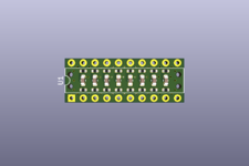
This is a recreation the discontinued Bourns 4120R-601-250/201 DIP used on the Macintosh SE and Macintosh SE/30. The filter chip also goes by the model numbers M/C 8908L 115-0002, CRL 8743L 115-0002 or P9120M115-0006.


Pictures of the chips:
1648527214916.png
1648527223573.png
1648527237107.png


Even though the Kicad and EasyEDA files are geared towards the 4120R-601-250/201 specifically, the capacitor and resistor values can be changed to make other discontinued Bourns 601 Series filters:

Part NumberResistor ValueCapacitor Value
4120R-601-101/101100 ohm100 pF
4120R-601-101/181100 ohm180 pF
4120R-601-101/201100 ohm200 pF
4120R-601-250/10125 ohm100 pF
4120R-601-250/18125 ohm180 pF
4120R-601-250/20125 ohm200 pF
4120R-601-250/50025 ohm50 pF
4120R-601-270/10127 ohm100 pF
4120R-601-270/20127 ohm200 pF
4120R-601-270/50027 ohm50 pF
4120R-601-470/10147 ohm100 pF
4120R-601-470/20147 ohm200 pF
4120R-601-470/50047 ohm50 pF
4120R-601-820/10182 ohm100 pF
4120R-601-820/20182 ohm200 pF
4120R-601-820/50082 ohm50 pF

If the part number your looking for isn't listed, please refer to the datasheet.


Bill of Materials​

4120R-601-250/201

QuantityDescriptionDesignatorsProduct NumberDatasheet
1625 Ohm resistor - 0402R1-R16
8200 pF capacitor - 0603C1-C8
210-pin male header 0.1" pitch
 

Attachments

  • 1648527168715.png
    1648527168715.png
    58 KB · Views: 71
  • Bourns_4120R-601-250_201.pdf
    225.8 KB · Views: 93

alasdairrr

New Tinkerer
May 12, 2022
1
0
1
View attachment 4038View attachment 4039

Got the assembled filters - the headers in the mail today from JLCPCB. Component placement and silkscreen looking good!
Hi alxlab,

Thanks for sharing this! Very handy - I'm in the process of populating one of Bolle's SE/30 boards and hoping to use as many new components as possible. I don't suppose the updated design was pushed to Github? I uploaded the Gerber files to JLCPCB (my first time attempting to do this) and the preview there only shows a single unit populated of the 8x3 grid:

Screenshot 2022-05-12 at 21.51.52.png


Cheers,

Alasdair
 

alxlab

Active Tinkerer
Sep 23, 2021
287
305
63
www.alxlab.com
Hey alasdairrr,

That's actually normal for panelized PCBs. The gerbers don't actually duplicate the whole PCB but provide the instructions on how to duplicate a single PCB into a panel.

Here's the past order that I did for 5 panels of 24 filters.
1652396384816.png

As highlighted on the image, they do something called a DFM Analysis after placing an order. When you click on it they will actually show a preview of the panel fully populated after an engineer reviewed the order.

1652397643829.png


NOTE!

I noticed that the part numbers on the BOM weren't exactly what JLCPCB was expecting so it was chosing the wrong resistor. Download the latest release to have the proper BOM.
 

JDW

Administrator
Staff member
Founder
Sep 2, 2021
1,245
1,108
113
53
Japan
youtube.com
Hey alasdairrr,

That's actually normal for panelized PCBs. The gerbers don't actually duplicate the whole PCB but provide the instructions on how to duplicate a single PCB into a panel.

I noticed that the part numbers on the BOM weren't exactly what JLCPCB was expecting so it was chosing the wrong resistor. Download the latest release to have the proper BOM.
What should the PCB thickness be when ordering? 1.6mm?

I added the ZIP file of Gerbers into PCBWay and it yields this odd preview:

1653227799762.png


Panel options are these:

1653227848883.png


or

1653227873567.png
 

alxlab

Active Tinkerer
Sep 23, 2021
287
305
63
www.alxlab.com
Morning JDW,

The release files (gerbers, bom, component placement, panelization) I added to the git repo were actually made for JLCPCB with EasyEDA. I should have been more explicit about that in my repo's README that it's Gear Towards JLCPCB. I did a quick look at the Kicad 5 settings specified by PCBWay vs JLCPCB and they don't match. The bill of materials also specified the JLCPCB Part # so you'll maybe need to change those if you use PCBWay

Regarding board thickness I used 1mm thick PCB to make it easier to snap the PCBs on the panels without added cost.

If it was JLCPCB I would chose the "Panel by Customer" option since I already did the panelization using their software. Alternatively if you didn't do the panelization in the design software you can chose "Panel by PCBWay" with "Break-away rail". I ended up going with 3 rows and 8 columns since it was the price/quantity sweet spot for me but maybe a different manufacturer will have a different sweet spot.

Let me know if have any more questions.
 

JDW

Administrator
Staff member
Founder
Sep 2, 2021
1,245
1,108
113
53
Japan
youtube.com
@alxlab
Thank you for confirming the importance of the 1mm board thickness. What I've found in a lot of Github projects is that board thickness isn't always specified, but it can be an important consideration for many applications.

Who chooses the capacitor dielectric? The BOM doesn't specify it. I would definitely go with C0G for the pF range if stability across temperature is important, but a PCB maker might choose X7R or a lesser grade if not specified. Whatever dielectric Bourns uses in its filter chips would be adequate, although I'm not sure what that is.

Although I am able to open the two JSON files in EasyEDA, I've not used it before, so the process of altering the Panelization for PCBWay is something I wouldn't want to engage in. I suppose I will need to email PCBWay, point them to the files on your Github and ask how they will handle it.
 

alxlab

Active Tinkerer
Sep 23, 2021
287
305
63
www.alxlab.com
@alxlab
Thank you for confirming the importance of the 1mm board thickness. What I've found in a lot of Github projects is that board thickness isn't always specified, but it can be an important consideration for many applications.

Yeah I really hate that too. I committed the sin by being in a rush to put the repo up and not specifying 😓

Who chooses the capacitor dielectric? The BOM doesn't specify it. I would definitely go with C0G for the pF range if stability across temperature is important, but a PCB maker might choose X7R or a lesser grade if not specified. Whatever dielectric Bourns uses in its filter chips would be adequate, although I'm not sure what that is.

Actually I did choose the specific parts in the BOM and most manufacturers allow you to specify or supply the specific parts. For the JLCPCB BOM that I supplies, the part number is the "Supplier Part" column. The capacitor in the BOM is currently pointing to JLCPCB Part # C1600
1653366016351.png


The original capacitor is temperature class is Z5U so C0G would be real overkill. It's really interesting how the Boruns datasheet actually gives this info in their datasheet.

1653366095132.png


I actually include the datasheet in my github:

https://github.com/alxlab-zone66x/B.../docs/datasheets/Bourns_4120R-601-250_201.pdf

Although I am able to open the two JSON files in EasyEDA, I've not used it before, so the process of altering the Panelization for PCBWay is something I wouldn't want to engage in. I suppose I will need to email PCBWay, point them to the files on your Github and ask how they will handle it.

PCBWay has a page to say how to format the BOM for them but that would be great if an engineer could help out.

EasyEDA has tight integration with JLCPCB in particular which is the main reason I used it. I don't know how easy it would to use it to produce files for another manufacturer.

I did include the Kicad 5 project files as an alternative. Since Kicad has no built in way to do panelization it would be best to allow them to do that for you like you showed before in the screen capture.
 

Attachments

  • Bourns_4120R-601-250_201.pdf
    225.8 KB · Views: 48
  • Like
Reactions: JDW

JDW

Administrator
Staff member
Founder
Sep 2, 2021
1,245
1,108
113
53
Japan
youtube.com
@alxlab
Thank you for the details. Very interesting that the 200pF capacitance value isn't critically important, as per their use of a rather horrible Z5U dielectric.

1653368424807.png
1653368442322.png


Since the Bourns datasheet specifies ±30% tolerance, that would mean whoever wants an assembled PCB using your design would need to choose the "M" (±20%) tolerance for a Z5U capacitor's since "Z" tolerance would be +80% and -20%.

X7R is the best of that category of dielectrics, but even it suffers tremendously from bias voltage, where you could easily lose up to 80% of the capacitance, depending on the rail voltage used. C0G are great not only because the specs are stable across normal operating temperatures, but especially because they don't have the bias voltage problem. With C0G, you would get 200pF regardless of the voltage used outside the "chip".

If you plug in 25Ω for R and 200p for C in this RC filter tool, the Bode diagram shows the cutoff frequencies. Change the value of C up & down to see how the cutoff (decline in the Bode graph) shifts left or right.

Anyway, I will contact PCBWay to see what they have to say. Thanks!
 
  • Like
Reactions: alxlab

alxlab

Active Tinkerer
Sep 23, 2021
287
305
63
www.alxlab.com
Yeah might as well use C0G since the price difference is negligible for low production runs.

I just updated the github README to include better BOM info and a Manufactuing section mentioning the release files for are JLCPCB specifically and 1mm PCB thickness.
 
  • Love
Reactions: JDW

JDW

Administrator
Staff member
Founder
Sep 2, 2021
1,245
1,108
113
53
Japan
youtube.com
View attachment 4038View attachment 4039

Got the assembled filters - the headers in the mail today from JLCPCB. Component placement and silkscreen looking good!
Still pondering this. One obstacle is cost and waste. You see, all the major PCB makers require no less than a 5pc order, which means 5pcs of the panel, which yields a whopping 120 Bourns Filters! I realized that one SE motherboard takes 4pcs, but 120pcs/4 = 30 motherboard's worth! I personally wouldn't ever use that many. What did you do with the extra pieces?
 

alxlab

Active Tinkerer
Sep 23, 2021
287
305
63
www.alxlab.com
Yeah, end up with quite a few if you want to decrease the cost of each individual filters.

I basically kept all the filters as spares and to possibly sell some in the future. If you're interested I could sell you some. Not exactly sure what the postal situation from Canada to Japan is at this point (Japan to Canada via Japan Post is still letter mail only) or the cost, but I could investigate.
 

JDW

Administrator
Staff member
Founder
Sep 2, 2021
1,245
1,108
113
53
Japan
youtube.com
The reason I asked about your excess PCBs is twofold.

First, my video series on the SE Reloaded project has given me knowledge about replacement chips. For example, @max1zzz created a replacement for the ROM chips. Kai created replacements for the ADB and SWIM. And of course you created replacements for the Bourns. All of that requires a purchase from a PCB maker (not to mention the purchase of a programmer too). But you see, most people doing projects like SE Reloaded are individual hobbyists. I would say the vast majority of people would want to build one board. Maybe two two SE boards tops. And yet, in order for them to create PCBs of anything, they must purchase no less than 5 pcs of the PCB. For small boards, that isn't too costly perhaps. But they couldn't make a big board like the SE Reloaded board because 5pcs of that, even without gold ENIG or matte black options would still cost a princely sum. Licensing terms prohibit them from selling excess SE Reloaded boards, so they would be stuck with 5pcs, if they wanted to buy a black matte version with gold ENIG -- a version that neither Kai nor MacEffects currently has. And on top of that, to make the ROM and ADB and SWIM chip replacements, they'd need to spend $70 or more on a TL866 II Plus programmer and socket module kit, which doesn't make much sense if one wishes to only program a handful of chips and then nothing ever after that. And all that doesn't even include the cost of new parts which they will need to buy to populate the SE Reloaded board like I did -- no less than $100 in parts.

Second, I was approached by PCBWay to advertise for them on my channel several weeks ago. I've not said yes yet because I would feel an obligation to help them and to help my viewers too. But I know the needs of my viewers because I am an individual hobbyist just like them. The 5pc order minimum just wouldn't be realistic most of the time. Buying 5 panels and ending up with 120 Bourns replacements doesn't make much sense. And although PCBWay explained the reason for the 5pc minimum by saying the build procedures are the same for 5pcs as for 100pcs, that explanation doesn't eliminate the fact that most people just want one or two PCBs of something (4pcs in case of the Bourns for one Mac SE motherboard). So if I advertised for PCBWay with this in mind, I probably wouldn't be helping them so much because most of my viewers probably wouldn't order in light of the 5pc minimum. And I wouldn't be doing my viewers any good either because I would be advertising a service they probably wouldn't use due to that order minimum.

So there is the conundrum. I want to help my fellow vintage Mac loving hobbyists, but how?

MacEffects is authorized to sell the SE Reloaded board, which is a partial solution for people who only want 1 board, at least, for people who like Glossy Red. But nobody is selling the ROM or ADB or SWIM replacements (Kai hasn't open-sourced the SWIM yet because nobody has tested it), and no one is selling your Bourns filter replacements either. Perhaps MacEffects could do that eventually, I suppose, if they were given authorization. But for now, that isn't an option. So in my SE Reloaded Part III video, I merely pointed out to people there are various Github pages with Gerber files available for download (I didn't mention your Bourns project though). But due to what I just explained, few people would likely choose that path.

I'm just trying to figure out a way to help individual hobbyists enjoy the hobby while at the same time get them to recognize the great people such as yourself who spent a lot of time creating these almost magical chip and board replacements.

I'd love to hear some proposed solutions for the good of the community. But for now it's a hard problem to solve.
 

max1zzz

Moderator
Staff member
Sep 23, 2021
230
539
93
27
FWIW I think the creators of most of these projects will sell small quantitys and possibly assembled / partially assembled / programmed ones if contacted (parts and time permitting) If anyone wants a assembled one of my SE ROM replacement boards please fell free to contact me, I have pleanty of boards and all the parts needed to assemble them

However one thing to consider is some / many of these projects where never done with the idea of them being a commercial product, my ROM boards are a good example of this - I designed them because I needed a set of FDHD ROM's and posted them online because i thought they might be of interest to others building reloaded boards

I sometimes think I should setup a shop selling the various bits and pieces I have designed, but haven;t found the time to do it.
 
  • Like
Reactions: trag and JDW

alxlab

Active Tinkerer
Sep 23, 2021
287
305
63
www.alxlab.com
Regarding the filters in particular, it would take someone to step up to actually take the trouble to sell these. This means breaking the panels into individual pcbs, cutting the 2.54mm pitch headers (if needed), packaging and shipping. I was thinking that maybe $1 - $1.50 CAD would make sense for the un-assembled (headers not soldered) filters? I strongly believe these need to be cheaper than the real 4120R-601-250/201 chips or else what's the point? Shipping will surely cost more than the four filters needed for a single Macintosh SE board but I guess the same would go if you bought the filters from utsource.net or the like.

The filters are sort of a special case since they can't be hand soldered so in order to be economical a batch needs to be made to spread out the assembly costs per unit.

Actually the header can assembled by JLCPCB as well but I've never actually tried their hand assembly and I'm not 100% sure of the cost. Likewise if you use other manufacturers they might be able to assemble the whole thing and separate all the individual board from the panel for you, Having to manually separate the panels into individual pcbs is a limitation of JLCPCB's manufacturing process. I've always found JLCPCB to be the cheapest to make the PCBs for my projects but for making a final commercial version of the Bourns filter it might might sense to look elsewhere.

Regarding the licensing of the Bourns filter, I actually made it CC-BY on purpose to make it easier for people to make and sell these commercially. I considered these a basic component so it should be as open as possible to help it spread. I still spent time doing the design though, hence the attribution part of the license so people can see the other projects I've done.

However one thing to consider is some / many of these projects where never done with the idea of them being a commercial product

In general I think most people that mark their projects as non-commercial are not against selling the projects commercially. It's more of a way to add some protection from people from selling their projects for a profit without compensating them. Usually it just takes contacting the project owner first to reach an agreement for commercial sale.

Personally I would be open to allow people to sell any of my projects commercially if they contact me first.

I sometimes think I should setup a shop selling the various bits and pieces I have designed, but haven;t found the time to do it.
I do intend to open up an online store on my website at some point to help recoup some of the costs from all these projects. I would consider it like giving a donation but you get stuff in return :D. In the mean time though I could sell stuff if I'm messaged directly.


I think @JDW highlighted all the possible cost issues associated with doing and SE Reloaded board. The sum of the parts would end up being more expensive than just buying a replacement SE board. Even you just wanted to transfer all the parts from a working SE board to the SE Reloaded board the time cost is high. For me personally even the time cost is to high to justify. Now that being said, I think that the SE Reloaded in the current market only make et more for people who understand the component and time cost and are willing to do it anyhow since it's a hobby or they want learning experience.

So there is the conundrum. I want to help my fellow vintage Mac loving hobbyists, but how?

@JDW I think the fact that making a video that shares all the knowledge around doing a SE Reloaded board, along with the caveats you mentioned above, is actually a great service to Mac hobbyist community. It brings a deeper understanding for the tools, processes, work and costs involved with such an endeavor. By highlighting the issues you ran into hopefully it will bring new solutions from people with different skills and experience.

I got sucked into all this Mac stuff about a year ago when I wanted to replace the 1/2 batteries in my dad's Mac SE. That lead to seeing the need for an alternative the 1/2AA batteries. That then ended up in the creation of the 1/2AA to CR2032 adapter which was my first time using Kicad and actually manufacturing a pcb. Since then I've learnt component assembly with the Bourns' filter and done many more projects thanks to the support and knowledge of people in the Mac community like you.

I'm just trying to figure out a way to help individual hobbyists enjoy the hobby while at the same time get them to recognize the great people such as yourself who spent a lot of time creating these almost magical chip and board replacements.

Well if you wanna help me I guess the best thing to do would be sending money 😂 Seriously though just sharing my projects or website would be more than enough. By sharing I'm hoping new ideas and solutions can stem from them. I'm also alright if you mentioned that I'm selling these filters. I guess the easiest way to contact me for buying stuff is on this forum or the TinkerDifferent discord.


Went through a lot of different thoughts and topics in this post. Hopefully what I wrote isn't too disjointed.
 
  • Love
Reactions: JDW

JDW

Administrator
Staff member
Founder
Sep 2, 2021
1,245
1,108
113
53
Japan
youtube.com
Thank you for sharing those detailed thoughts, gentlemen.

Because the Reloaded build costs more in time and money than a $140 SE board sold on EBAY, I mention that fact in my videos, suggesting people think of it instead as a thrilling project whereby they are building the heart and soul of a vintage Mac. When you ponder it that way, it becomes a worthwhile and fulfilling project.

What I found in the SE Reloaded Build was that the prep time took me the longest. I did not calculate that time in my videos because that was work I did so others wouldn't have to repeat what I went through. Basically, making sure you have all the right parts from reliable vendors is key. Kai's BOM was only a starting point for me. I discovered a few BOM mistakes, but all that has now been fixed. Also, since there is no single vendor from which you can buy all the parts, I had to spend a lot of time figuring out the best places to get the parts, and determine that all the part numbers were 100% accurate. Sourcing is hard and time consuming, let me tell you. And the global parts shortage complicates and already hard thing quite a bit.

Kai of course helped me out a lot when I was buying all the parts, and he very graciously shipped me some parts too (not to mention a couple Reloaded boards and even an entire Mac SE). But I needed to compile the complete set of info for other people who wouldn't be receiving any parts from Kai.

In the end, I found that most parts can be purchased on Mouser, with other parts needing to be purchased from the AXXOS Atari Store in the UK, UT Source in China, Amazon, and possibly EBAY. I compiled all the parts info, including details about the chip replacement projects of @alxlab and Kai in this document, which is linked in the text description under my Reloaded videos. I even spent time adding "location info" which wasn't in Kai's original BOM, which is a real productivity enhancer when you are soldering in numerous parts across an entire motherboard.

If ever replicas of the metal bracket, SONY snd chip, and the plastic stands for the Reset and Programmer's switches come out, then that would eliminate most anything you would need to solder from the stock board. (Philippe Astier from France told me a few days ago he is thinking about work a 3D printable model for the switches, by the way.)

I haven't mentioned this Bourns replacement project thread yet in my parts list document mainly because I found that UT Source carries them. But the bigger problem was that I didn't know how to resolve the issue people would face of having to buy 5pcs of a PCB panel. Most people wouldn't buy that many, nor wish to hand-build 120pcs. But should someone become authorized to sell individual parts kits or completed bourns filters (similar to the way BlueSCSI is sold), then I can add that info because it will then become useful for SE Reloaded builders.

By the way, I bought my Bourns (shown in my video) from Mouser, just before Mouser terminated sales of that product; but man alive! I had to pay a whopping $6.15 per chip! And although UT Source sells them now, they charge $3.76 each with a min. order of 2pcs (keep in mind you need 4pcs for the SE board), and then you have to pay then $20 in shipping fees!

So you can see why having a lower cost, one-stop place to get the Bourns would help out a lot of people. That is really why I posted in this thread in hopes if stimulating thought on that issue, for the good of community members who want to buy them for an SE or SE/30 motherboard repair or build. (Mac Classic's user network filters too, but they are SMD.)

While the SE Reloaded project requires soldering skills, it is in fact the acquiring of all the right parts that is key to finishing a build. And while some parts might still be good and able to be desoldered from the stock board, desoldering is many times harder (when done right) than soldering new components to a new board, so limiting that painful work is best.

My parts list is a Google Docs file, so I can add new info to it over time. I am happy to provide a link to a sales page when and if there is ever a vendor of a chip replacement kit or pre-assembled part becomes available.

Thank you, gentlemen for all the work you do.
I would also like to thank @Stephen too, because he is very much involved in designing PCBs that have bettered the community in numerous ways.

Without those amazing custom PCBs (including Kai's reloaded PCBs), this hobby would still be around but be much less fun. SO THANK YOU!
 

alxlab

Active Tinkerer
Sep 23, 2021
287
305
63
www.alxlab.com
the plastic stands for the Reset and Programmer's switches come out

It's funny you mention that.... I actually just did the model for exact replica of that after I accidentally melted a switch. @Kay K.M.Mods surprised me with the part number of the original switch which happens to still be in production SKHCBHA010.


1656736085769.png
1656736095413.png


I actually placed several orders with JLCPCB to see how they will turn out. The original holder has 0.7mm thick walls. The manufacturing methods used by JLCPCB recommends at least a 1mm thick walls so I also made another model with 1mm thick walls. We'll see how that turns out in 2-4 weeks once I receive the orders. I'm thinking I could probably make another model which is not the same as the original but would be much easier to print with a cheap FDM 3D printer. I'll make a proper github repo and separate post on TinkerDifferent once I confirm everything looks good. In the mean time I've attached the two models for anyone keen.

There's also another model for the switch back here:
https://68kmla.org/bb/index.php?thr...cboard-recreation-thread-revival.39485/page-9

It made a compromise though by omitting the strain relief pins on the bottom to make 3D printing easier.

replicas of the metal bracket

Hmmm now that you mention it JLCPCB can do stainless steel 3D printing now... Probably won't be cheap but it's theoretically doable. Something to mull over.


Personally, to bring down the cost in time and money of the SE Reloaded board I would love to see or do an updated board with surface mount components for all the resistors and capacitors. Theoretically the filters could also just be assembled on the board and maybe leave the footprint for the dip packages just in case. CR2032 battery holder would be nice. Maybe chip sockets could also be assembled by the PCB manufacturer. Maybe one 72-pin simm socket could be used instead of 4 x 30-pin simm sockets.
 

Attachments

  • Macintosh Interrupt Switch Back.zip
    18.9 KB · Views: 71