
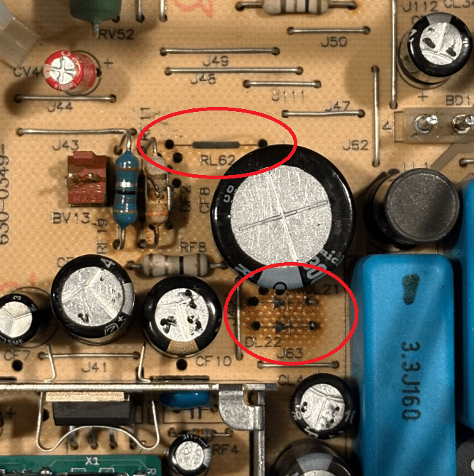
Over the years, there have been lots of discussions surrounding the infamous DL21 and DL22 18V Zener diodes on the Color Classic analog board and the damage they tend to induce over time from their high power dissipation. There's scorched PCBs, reduced life of nearby CF8, generally undesirable excess heating, to name a few. I think every original Color Classic analog board has probably been affected by now. While there are good solutions out there, like "beefy" component upgrades, I figured it was about time for a better 18V regulator solution. My apologies if someone in the community has already implemented something like this, but I just haven't seen it if so. I wanted to design something that was really simple and as much of a drop-in solution as possible. My solution is a small PCB with a few components, providing an emitter follower linear regulator. It has a small footprint, and crucially, can pop into the through-hole position of one of the original components, for both simple installation and mechanical stability.
Here's what I did:
First, completely remove RL62 and the two Zeners, DL21 and DL22 from the analog board. But don't lose the parts, because you can reuse RL62 and one of the Zeners on the custom regulator PCB.
Along with a 1k resistor and an MJE340 NPN transistor, the salvaged components can be assembled into the circuit shown below on the new PCBA:
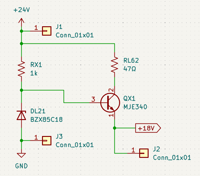
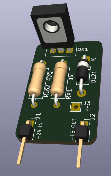
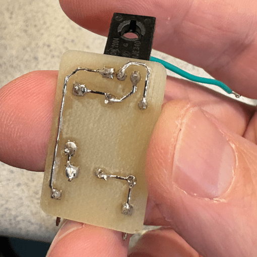
The original Zener just serves as a reference voltage in the new circuit with much lower bias current, rather than directly regulating the output. The MJE340 is a very simple emitter follower in this design. Other kinds of BJTs can certainly work, and the MJE340 is overkill in some ways, but it has a nice package for this purpose. The heatsink tab acts sort of as its own heatsink in this relatively low-power application. RL62 is used to drop some of the voltage from input to output and reduce the load on the MJE340, as well as provide current limiting in transient states. The two header pins match the spacing of the original RL62 through-hole location on the AB, which conveniently match up with nodes for the input 24V and output 18V. The one inelegant bit is the need for a ground connection that doesn't conveniently line up with the edge of the board, so for that connection I have a bare through hole for a ground pigtail. There is, however, a now-available ground through-hole connection on one side of the DL21/DL21 positions that's a good spot for the ground wire.
I've made a KiCad project for the board, which I'll share below. This board is simple enough that I was able to machine one from single-side clad FR-4, though you can get one made with an outside PCB fab. You could also easily implement it on some proto-board with bodge wires. The header pin spacing is very close to 1/2", so 5-hole spacing should do the trick on 0.1" proto-board.
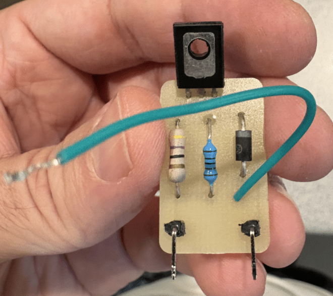
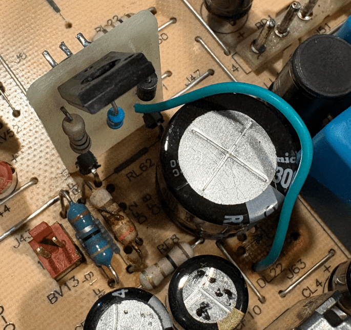
Installed! I've been running this on one of my CCs for about a day and it's been working great. By my measurements and calculations, this should reduce the power dissipation from about 2.2W in the original Zener regulator circuit (power in RL62 and the Zeners) to about 0.36W (mostly in the MJE340 and RL62), a 6X reduction! The power that is dissipated is relatively far from the AB, and importantly, far from any electrolytic caps, especially if you bend the MJE340 up slightly. One other thing to note: technically, this will produce an output voltage that's actually around 17.3V, due to the Vbe drop of the MJE340. I haven't seen any noticeable difference in raster (the 18V supply is mostly used in the vertical section), but if you really want to hit the nominal 18V as close a possible you can either use a different ~19V Zener, or put a forward-biased PN diode in series with the 18V Zener to compensate.
Link to the KiCad project: 18V_Regulator_1.0.zip
If you try this out, please let me know how it works out for you
Here's what I did:
First, completely remove RL62 and the two Zeners, DL21 and DL22 from the analog board. But don't lose the parts, because you can reuse RL62 and one of the Zeners on the custom regulator PCB.
Along with a 1k resistor and an MJE340 NPN transistor, the salvaged components can be assembled into the circuit shown below on the new PCBA:
The original Zener just serves as a reference voltage in the new circuit with much lower bias current, rather than directly regulating the output. The MJE340 is a very simple emitter follower in this design. Other kinds of BJTs can certainly work, and the MJE340 is overkill in some ways, but it has a nice package for this purpose. The heatsink tab acts sort of as its own heatsink in this relatively low-power application. RL62 is used to drop some of the voltage from input to output and reduce the load on the MJE340, as well as provide current limiting in transient states. The two header pins match the spacing of the original RL62 through-hole location on the AB, which conveniently match up with nodes for the input 24V and output 18V. The one inelegant bit is the need for a ground connection that doesn't conveniently line up with the edge of the board, so for that connection I have a bare through hole for a ground pigtail. There is, however, a now-available ground through-hole connection on one side of the DL21/DL21 positions that's a good spot for the ground wire.
I've made a KiCad project for the board, which I'll share below. This board is simple enough that I was able to machine one from single-side clad FR-4, though you can get one made with an outside PCB fab. You could also easily implement it on some proto-board with bodge wires. The header pin spacing is very close to 1/2", so 5-hole spacing should do the trick on 0.1" proto-board.
Installed! I've been running this on one of my CCs for about a day and it's been working great. By my measurements and calculations, this should reduce the power dissipation from about 2.2W in the original Zener regulator circuit (power in RL62 and the Zeners) to about 0.36W (mostly in the MJE340 and RL62), a 6X reduction! The power that is dissipated is relatively far from the AB, and importantly, far from any electrolytic caps, especially if you bend the MJE340 up slightly. One other thing to note: technically, this will produce an output voltage that's actually around 17.3V, due to the Vbe drop of the MJE340. I haven't seen any noticeable difference in raster (the 18V supply is mostly used in the vertical section), but if you really want to hit the nominal 18V as close a possible you can either use a different ~19V Zener, or put a forward-biased PN diode in series with the 18V Zener to compensate.
Link to the KiCad project: 18V_Regulator_1.0.zip
If you try this out, please let me know how it works out for you
