Copper fingers on the SE/30 board?
- Thread starter Cam
- Start date
-
Please can you read through and vote on the following proposition for changes to the board structure by clicking here.
You are using an out of date browser. It may not display this or other websites correctly.
You should upgrade or use an alternative browser.
You should upgrade or use an alternative browser.
Do you mean the 15-pin ISA edge connector at the front side of the SE/30 logic board as circled in red?

@Cam, that edge connector on the SE/30 logic board is exclusively used to test the logic board at one of the Apple factories, like in Fremont, California, back in the day. It has no practical use for end users.
On the reloaded SE/30 board, that area lacked the edge connector and was used as optional PLCCs for the four ROM chips.
Paging @Bolle as he is the expert with SE/30 boards and probably will have more to say.
On the reloaded SE/30 board, that area lacked the edge connector and was used as optional PLCCs for the four ROM chips.
Paging @Bolle as he is the expert with SE/30 boards and probably will have more to say.
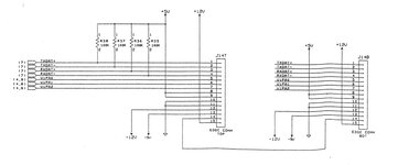
Does anyone know the pinout of the 15-pin ISA edge connector ? I've searched online and can't find anything.
I thought it would make for good test points - I am troubleshooting an SE/30. So far I've figured out pins 8 and 9 are +5V and pins 10 and 11 are ground but thats it. Didn't find +12V, -12V, vertical sync, horizontal sync, video signal - I was checking for continuity between the pins on J12 and the 15 pin edge connector.
I'm hoping to connect my logic probe up to check some signals.
Last edited:

