CRT width

iantm

Tinkerer
Sep 8, 2025
144
64
28
Great Lakes
This seems basic, but one of my analog board TDA1170N chips seems to have failed, so I swapped out a different analog board. The geometry was way off. I can adjust the height, the focus, brightness, and the yoke magnets. But the width won't change. Is the pot for the width broken?

I've ordered a couple of replacement TDA1170N chips and a set of CRT universal adjustment tools… I'm hoping that's all it is.
 
  • Like
Reactions: phunguss

jonschultz

New Tinkerer
May 16, 2026
23
14
3
USA
github.com
I'm not too familiar with the TDA1170N, but it looks like it's a vertical deflection IC, similar to other ones that I've seen. I don't think any of the horizontal deflection functions are handled by this IC, so it wouldn't have any effect on the width of the raster (though, a caveat would be that it might have some influence on the pincushion correction, which does modulate width). In any case, I think it's more likely that something else broke in the process of swapping the part. Is the width currently in sort of a normal state, or is it way off?
 
  • Like
Reactions: iantm

iantm

Tinkerer
Sep 8, 2025
144
64
28
Great Lakes
It’s not too far off, but I can’t adjust it at all with the analog board pot.

According to the dead Mac scrolls, 1170n controls horizontal deflection and when it fails you get nothing but a flat bright horizontal line.

That’s why I swapped analog boards. But the new one can’t be adjusted horizontally for some reason.
 
  • Like
Reactions: jonschultz

jonschultz

New Tinkerer
May 16, 2026
23
14
3
USA
github.com
I see, but a bright, horizontal line means that vertical deflection has failed. Horizontal deflection is still working just fine in that case. Failure of horizontal deflection almost always results in absolutely nothing on the CRT functioning because a lot of the circuitry depends on the flyback being driven by the horizontal deflection.
 

Mark_W

Tinkerer
Feb 2, 2026
34
29
18
Horizontal width is controlled by the width coil, not potentiometer.

I assume you are talking about the vertical height of the image, in that case clean the height adjustment potentiometer with contact cleaner, make sure it's not damaged and is actually turning, you should see the wiper arm rotating from the component side of the analog board when you turn it. There are only 2 components in the height adjustment circuit iirc, so should be easy to identify the cause.

Also for the other board with horizontal line, reflow the yoke connector first if you haven't done so. Also when swapping analog boards I always swap the yoke with it, since all adjustments are specific to the yoke it paired with originally.

Btw you can find replacements on aliexpress for like $1 each, bought a lot before and haven't got any issue, but keep in mind many chips on aliexpress are used/recycled
 
  • Like
Reactions: iantm

iantm

Tinkerer
Sep 8, 2025
144
64
28
Great Lakes
I think the two problems have been a mixed up a bit. But yeah: one board either needs the deflector chip (tda1170n) replaced or the yoke reflowed because the raster has collapsed to a horizontal line.
The working analog board might need to be retuned, as I have no idea which board pairs with which yoke.
Hopefully I can adjust the width coil on that one. The height, brightness and focus work fine on that board. I have to figure out why I can’t adjust the width.
 

iantm

Tinkerer
Sep 8, 2025
144
64
28
Great Lakes
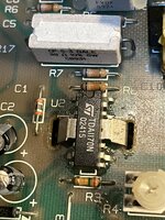
A tale of three analog boards:

Analog Board A was failing vertical raster. Flat horizontal line. Replaced the TDA1770N chip, reflowed the solder on the whole board. Still flat. Tried another board:

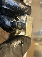
Analog Board B worked, but the geometry was off. I wasn't able to adjust the width coil with what I had, so I bought a universal CRT adjustment kit. The hex tool in the kit made it possible to adjust the width easily. But for some reason I'm getting no sound through the speaker with this board. Headphones are fine. I tried two different logic boards. Only swapping in the last analog board worked:

Analog Board Crecapped back in October, works, thank goodness. Sound + geometry.

I'll get back to figuring out A & B later. Any thoughts welcome.
 

Attachments

  • IMG_9036.jpeg
    IMG_9036.jpeg
    1.5 MB · Views: 1
  • IMG_9035.jpeg
    IMG_9035.jpeg
    1.2 MB · Views: 1

Mark_W

Tinkerer
Feb 2, 2026
34
29
18
I assume you are repairing the analog board of se30 right? Check -12v output of psu and on logic board. if there's no -12V you won't get any sound as the opamp used for audio amplification requires -12V.

For analog board A, trace Vsync signal with an oscilloscope, make sure it reaches TDA1770. Could be a dead NAND gate in U1. Also check +12v supply and surrounding circuit, there are only around 10 components in total iirc, should be easy to diagnose