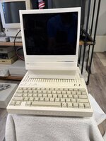
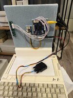
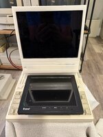
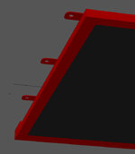
Custom USB-C powered 8"display for the Apple IIc with STL files and build plan

JDW

Administrator
Staff member
Founder
Sep 2, 2021
2,366
1,900
113
54
Japan
youtube.com
It would be wrong for changes to be made only for me, so I agree there needs to be feedback from other Apple IIc owners.
Maybe @Javmast3r would like to chime in?

Before any changes are made, it might be best for @ArjenCNX to test the compact A2VI adapter on his machine first (only if he wants to, of course). The purpose to test that adapter on his setup is twofold:

1. To see if it improves vertical centering and offers a larger displayed image on his 8" Eyoyo (just as it does on my 10" knock-off Eyoyo), and
2. To see if that compact A2DVI adapter would fit inside a modded version of his plastic enclosure.
 
  • Like
Reactions: ArjenCNX

wottle

Active Tinkerer
Oct 30, 2021
805
552
93
48
Fort Mill, SC
I'm willing to make the needed modifications to the existing design, if you can reach some consensus on what would be best, and provide that to me, then i can adjust the current design if needed. to power the computer from the single USB-C plug should not be an issue either.
I’ve ordered your existing 3d parts from JLCPCB in their white resin. I’m planning on using the 8” screen I found on Amazon that appears to be the correct model. I plan on trying to set up my UsB C trigger board to request 15v and then try to find a spot to drop in a buck converted to drop the voltage to 12v for the LCD. So one 15v line will run out the case to a pigtail cable that will power the IIc, then a second 15v line that will run to the buck converter with 12v out to the LCD. I’ll let you know how it goes and see if any changes are even necessary. I don’t mind putting a new hole in the case for a wire. The question will be if there’s room for that buck converter. I’ll let you know how it goes.
Thanks again for doing this.

One other question: did you consider running it from the video out port? I have an adapter I made that plugs into an aftermarket LCD and if I’m remembering correctly, I was able to pull 12v off that port, along with the composite video signal so I just had to plug one cable in to get everything I needed. I’ll take a look at what I built when I get home tonight.

EDIT: it looks like the 12v out on the monitor port only does 300mA and the new monitor wants 1000mA. So I’ll go with my original plan of powering both off USB-C and having a pigtail cable to plug into the port for powering the IIc.
 
Last edited:
  • Like
Reactions: JDW

ArjenCNX

Tinkerer
Oct 20, 2025
28
27
13
I’ve ordered your existing 3d parts from JLCPCB in their white resin. I’m planning on using the 8” screen I found on Amazon that appears to be the correct model. I plan on trying to set up my UsB C trigger board to request 15v and then try to find a spot to drop in a buck converted to drop the voltage to 12v for the LCD. So one 15v line will run out the case to a pigtail cable that will power the IIc, then a second 15v line that will run to the buck converter with 12v out to the LCD. I’ll let you know how it goes and see if any changes are even necessary. I don’t mind putting a new hole in the case for a wire. The question will be if there’s room for that buck converter. I’ll let you know how it goes.
Thanks again for doing this.

One other question: did you consider running it from the video out port? I have an adapter I made that plugs into an aftermarket LCD and if I’m remembering correctly, I was able to pull 12v off that port, along with the composite video signal so I just had to plug one cable in to get everything I needed. I’ll take a look at what I built when I get home tonight.

EDIT: it looks like the 12v out on the monitor port only does 300mA and the new monitor wants 1000mA. So I’ll go with my original plan of powering both off USB-C and having a pigtail cable to plug into the port for powering the IIc.
Really cool sir! do share the pictures, im curious how nice it will look in resin print! SLA could also be nice i think, but there is not much choice for colour. (would work well in black though)

for the monitor it takes about 350mA at max brightness, so less then 1A, but more then 300mA.

I run the monitor straight off the composite output in to the BNC pad of the monitor PCB through a small coaxial cable. for the buck converter, you could surely fit it inside the monitor, usually they would be too thick to fit in the base, also best get something more then 90% efficient.

also, how to place the inserts in resin? i have not tried that before, it may have to be glued in
 

wottle

Active Tinkerer
Oct 30, 2021
805
552
93
48
Fort Mill, SC
Really cool sir! do share the pictures, im curious how nice it will look in resin print! SLA could also be nice i think, but there is not much choice for colour. (would work well in black though)

for the monitor it takes about 350mA at max brightness, so less then 1A, but more then 300mA.

I run the monitor straight off the composite output in to the BNC pad of the monitor PCB through a small coaxial cable. for the buck converter, you could surely fit it inside the monitor, usually they would be too thick to fit in the base, also best get something more then 90% efficient.

also, how to place the inserts in resin? i have not tried that before, it may have to be glued in
Good point. I forgot you had brass inserts. I may need to do a bit of drilling and glueing. I'll let you know how I get it put together. It may be a few weeks. JLC3DP usually takes 2-3 weeks to get here with the cheap shipping option.
 

ArjenCNX

Tinkerer
Oct 20, 2025
28
27
13
the top corner holes have an ID of 4.5mm my inserts have an OD of 5mm, but you can grind them down to 4.5 without too much issue and glue them in with super glue i think. (you can get a long M3 bolt, screw them on and then put it in a drill, you can then use sand paper or probably even a combo pliers to grind them down to the required OD. for the M2 inserts the ID is 3.2mm, the inserts have 3.45mm OD so same there, you can grind them down a little. this is much preferable to drilling the print, as you can try a few times with cheap inserts till you got it right without risking your print. for the Bezel the ID is 5.5mm but the insert is 7mm in OD adjusting it to fit will be more challenging there but this part is very solid and provided you are very careful you should be able to drill that out, best use a very sharp drill, single flute if you got them. also remember this must be a snug fit, it will be tensioned, so best not over drill there and use epoxy to glue it. fill the insert internally with some grease or anything else suitable to prevent the glue from making it impossible for the screw to fit the threads.

please measure the inserts you have on hand to verify my measurements.

Should i make a design specially for resin printing? i can adjust all these things in design so the inserts are glue-fit instead of melt-in

also, the side plates are fastened with M3 screws, with extrusion filament print this is file because the materials are ductile, but the resin print they are not, so i suggest tapping the holes there to make them accept M3 screws.
 
Last edited:

wottle

Active Tinkerer
Oct 30, 2021
805
552
93
48
Fort Mill, SC
I actually watched this video and it seems like the resin prints may be ok with just screwing directly into the part. But that may not work with the current models as the holes were setup to accept inserts, not the screws themselves. I'll let you know when they arrive how it work. Hopefully I can get it to work properly - I've been a big fan of the finish of the resin prints I've ordered, and it was actually cheaper than the FDM prints from JLC3DP. Thanks again for putting this together!
 
Last edited:
  • Like
Reactions: JDW

JDW

Administrator
Staff member
Founder
Sep 2, 2021
2,366
1,900
113
54
Japan
youtube.com
I found it on Ebay https://www.ebay.com/itm/267198515931, I'm based out of northern Thailand, on the Asian webshops they are readily available
So you didn't buy from the EBAY seller and instead bought it from an "Asian web shop"?

The reason I ask is because that EBAY seller only wants to sell to the USA...

1762230361709.png


1762230385927.png


He advertises it as being an "IPS" display.


The lower cost version on AliExpress that looks exactly the same (if the photos are not fake) is here...

1762230448838.png


But the lone review is only 2 stars, and he appears to be a vintage computer user as well...

1762230492060.png


He claims it is TFT, not IPS. Is your experience with your Eyoyo the same as his?

My 10" Eyoyo Knock-off isn't showing "image retention" that I can see. Mine is also IPS, not TFT like the above reviewer mentions. But I didn't buy the one that reviewer bought. And it very well could be that his Eyoyo is a fake too, albeit a bad one.

@wottle seems to have purchased this one on Amazon, and that is advertised as being TFT. So I guess it's the same as the 2-star one on AliExpress, and I therefore eagerly await hearing what wottle thinks of it.
 

ArjenCNX

Tinkerer
Oct 20, 2025
28
27
13
Hmmm... it was a long time ago i bought this, so forgive me for not remembering the exact vendor, i suspect i got it from lazada locally. however, amazon has their official store, so im quite sure that should be original.
 

JDW

Administrator
Staff member
Founder
Sep 2, 2021
2,366
1,900
113
54
Japan
youtube.com
It’s also important to consider that the 8 inch Eyoyo model (TFT) appears to be 800 x 600 resolution, whereas the knockoff 10 inch version that I have (IPS) is 1024 x 768 resolution.
 

phunguss

Active Tinkerer
Dec 24, 2023
472
405
63
57
Stillwater, MN
I have confirmed my Eyoyo 8" is authentic and works with the A2CDVI. I also have a few recovered iPad 1/2 screens with driver boards. Native resolution is 1024x768, but with the A2CDVI, it seems to display fine. Here is a photo with my poorly CNC'd Acrylic front to emulate an Apple Cinema Display in miniature.
ACD-mini3.jpg

ACD-mini4.jpg

So, I will take the STL files and try to modify it for a 9.7" iPad screen ( I just bought 4 more broken iPad 1/2 on Craigslist for $20, and ordered display driver boards from China via eBay... lets see what happens with the tariffs).
ACD-mini1.jpg

ACD-mini2.jpg
 
  • Like
Reactions: JDW

ArjenCNX

Tinkerer
Oct 20, 2025
28
27
13
That display is different from the one i used, mine has a LCD with flat-flex connect to the PCB, and the PCB looks quite different as well. Since im using composite video in, i guess resolutions doesnt matter all that much but mechanical dimensions may differ. its also possible the manufacturer has different revisions of course.
 

JDW

Administrator
Staff member
Founder
Sep 2, 2021
2,366
1,900
113
54
Japan
youtube.com
its also possible the manufacturer has different revisions of course.
Or multiple manufacturers, because it's really, REALLY hard to know these days what is genuine and what's a knock-off. For example, my 10" IPS display is branded EYOYO but the official EYOYO site makes no mention of it at all. Funny that. Mine is IPS, yet the 8" official product seems to be regular TFT. So even if you find an 8" display branded EYOYO, I wonder if it's genuine or not. And when mounting in a 3D printed bracket designed for a specific monitor shape, that can be an issue.
 

ArjenCNX

Tinkerer
Oct 20, 2025
28
27
13
Well, i remember when living in Shenzhen the sales girl asking, what brand do you want? while holding a box of nice aluminium brand lettering with Sony / Toshiba / LG / and so on. funny that was. there are hundreds of companies making monitors, often with recycled displays, where they take the LCD, replace the CCFL with an LED strip and then sell them in bulk. euh, i guess its... green?

i worked in Shenzhen for 4 years, spend 15 in china altogether. i used to do IC testing there building test circuits and setting up inspections for detection of used / fake / reclaimed parts.

Crazy times!
 

wottle

Active Tinkerer
Oct 30, 2021
805
552
93
48
Fort Mill, SC
That display is different from the one i used, mine has a LCD with flat-flex connect to the PCB, and the PCB looks quite different as well. Since im using composite video in, i guess resolutions doesnt matter all that much but mechanical dimensions may differ. its also possible the manufacturer has different revisions of course.
I think @phunguss' images were of his iPad screen and display controller board. That matches what I have been using with my Apple II (driven off the display out port to pass composite video and 12v to power it. I don't believe those pictures are of the 8"display (it's too wide), but it does match the width of my iPad 1 LCD that I've been using with mine. I've shown the 10" iPad screen with the 8" Eyoyo I got from Amazon in the 3rd picture. Still waiting on my enclosure prints to arrive, and my 3d printer is not producing great results at the moment, so I've just tested the Eyoyo separately for now and it looks good.

IMG_9607.jpegIMG_9609.jpegIMG_9610.jpeg

@phunguss, I am definitely interested in an altered version for the 10" iPad display, since I have the display and controller board, and I know it works with the voltage supplied directly from the A2 display out port. I'm not much of a 3d modeler, but if you need someone to help / test out a design, let me know.
 
  • Like
Reactions: JDW

phunguss

Active Tinkerer
Dec 24, 2023
472
405
63
57
Stillwater, MN
@phunguss, I am definitely interested in an altered version for the 10" iPad display, since I have the display and controller board, and I know it works with the voltage supplied directly from the A2 display out port. I'm not much of a 3d modeler, but if you need someone to help / test out a design, let me know.
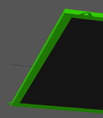
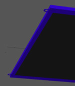
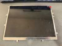
Yes, I will modify the design to fit the iPad screens (technically 9.7 inches). The three versions I have are all different sized (version 1-3), different mounting holes, and different bezel dimensions. @wottle let me know which version you have and I will work on that one first.

iPad gen 1 (red), 1024x768 resolution; iPad gen 2 (green) 1024x768; iPad gen 3 (blue) 2048x1536
iPad1-Red.jpgiPad2-green.jpgiPad3-blue.jpg
Combined overlay.
iPad-all-RGB.jpg
 
  • Like
  • Love
Reactions: wottle and JDW

wottle

Active Tinkerer
Oct 30, 2021
805
552
93
48
Fort Mill, SC
Yes, I will modify the design to fit the iPad screens (technically 9.7 inches). The three versions I have are all different sized (version 1-3), different mounting holes, and different bezel dimensions. @wottle let me know which version you have and I will work on that one first.

iPad gen 1 (red), 1024x768 resolution; iPad gen 2 (green) 1024x768; iPad gen 3 (blue) 2048x1536
View attachment 24580View attachment 24581View attachment 24582
Combined overlay.
View attachment 24583
No rush. I have the 8" version on the way. Although this would allow me to set up one on my IIc and one on my IIc+. It looks like I have the iPad 1 version, but feel free to work on them in any order that makes the most sense for you.
IMG_9618.jpeg
 

phunguss

Active Tinkerer
Dec 24, 2023
472
405
63
57
Stillwater, MN
No rush. I have the 8" version on the way. Although this would allow me to set up one on my IIc and one on my IIc+. It looks like I have the iPad 1 version, but feel free to work on them in any order that makes the most sense for you.
View attachment 24584
This is just an example, I would like to test print to make sure it fits before I attach the STL files. The only thing I have modified is the Bezel and Back, I left all the other parts as released by @ArjenCNX
Screen Shot 2025-11-08 at 2.43.57 AM.jpg

Screen Shot 2025-11-08 at 2.44.13 AM.jpg

Screen Shot 2025-11-08 at 2.46.43 AM.jpg
 
  • Like
  • Love
Reactions: wottle and JDW