Lisa 2 repair journey

rdmark

Moderator
Staff member
Oct 3, 2021
164
230
43
Earlier this year, a friend mentioned to me that he has had an Apple Lisa 2 in storage for many years, a machine that he acquired in the early 90s that had never worked properly for him. The symptoms, as he remembered them, was that the computer would turn on and run for a few minutes, and then turn off again. And sometimes it wouldn't turn on at all. In addition, it had suffered battery leak damage in storage, although it had been caught relatively early, luckily, with the battery removed some years prior. He casually mentioned that I could take a look at it and assess the damage, if I'd like to.

At that point, I had a track record of fixing a fair number of vintage computers in various stages of disrepair, but a battery damaged Lisa with other known issues would definitely be my biggest project yet, and on a really quite expensive/valuable piece of equipment to boot. This is a computer of which between 10,000 and 80,000 (depending on the source of the estimates) were ever sold, after all. I hesitated at first, and told him that I could look at it some day, but made no promises beyond that.

Then one day, after I had helped him fix another few computers of his for fun (Apple ][+, //gs, Mac 128k, and a few peripherals) we agreed that it was time to look at that Lisa. We pulled the old girl out of storage and lugged her over to my friend's apartment. Her profile may be low when viewed from the front, but she has a hefty backside. All those solid steel frames in there makes for one heavy piece of equipment!

PXL_20220410_002132722.jpg


Before proceeding further, I decided that it was time to assess the battery damage for starters.

All of the main logic circuitry of the Lisa sits inside of a conveniently located card cage just behind the back panel of the computer. The battery used to sit on the I/O board, which is the outermost card in the card cage.

PXL_20220327_005523935.jpeg


IMG_5064.jpg


Off the bat, the battery juice had clearly caused some damage to traces and components, but luckily it was fairly well isolated on this particular board. The most green crust could be found on the Motorola 1489 chip, but otherwise mostly on traces and solder joints. Pretty nasty, but manageable! (We did run into a bit of a surprise though; more on this later.)

Moving on to the Motherboard (yes, this is what Apple calls it on the silk screen and in documentation!)

IMG_5069.jpg


On the left hand side of this board we had some very sad looking traces, as well as a very very crusty (and weird-looking) resistor pack. This picture just quite don't convey just how dull all of the joints of RP2 was -- they looked more like granite than solder.

IMG_5070.jpg


Then moving on to the 120 pin socket that the I/O board sits in on the Motherboard, we had more of that green crust that made its way into the socket. I didn't take a before picture, but here is just after neutralizing it with vinegar. Just gently poking on the pins made them fall off. Rotten at the root. This socket needs to go!

There was also a bit of green corrosion on the edge connectors on the upper side of the Motherboard that I didn't snap a picture off, as well as in the slots leading to the Video board and Lite board (disk drive adapter.) Luckily, it could be neutralized and scraped off without further damage.

At this stage of the process, I put in an order with Mouser for replacement parts of clearly damaged components, and took a break while waiting for the shipment to arrive. In the next post, I will address the battery damage and take one step closer to a working computer!
 
Last edited:

rdmark

Moderator
Staff member
Oct 3, 2021
164
230
43
Time to deal with that battery damage! Special thanks to @Elemenoh in this episode for helping me identify several replacement parts.

Step one is always to neutralize the alkaline rot. Household white vinegar to the rescue. I use distilled vinegar diluted to 5% acidity. Here demonstrating my paper towel method, which is useful to apply localized treatment. I usually leave it like this for about 30 min, which seems to about enough to make it react with the base chemicals in the battery leak and turn green crust into black crust.

IMG_5061.jpg


The edge connector on the I/O board was luckily salvageable, with plenty of good copper left after corrosion was removed.

Next, to remove the components which are visibly affected by corrosion. For small components like this, a desoldering pump is adequate. I use a cheap SOLDAPULLT brand manual pump by Edsyn, which apart from a ridiculous name gives you an excellent bang for the buck at less than $25.

IMG_5066.jpg


Here, I started going over the traces, vias and through holes with a hobby knife to gently scrape off contaminated solder mask. I then applied the solder wick scrub method, where you apply a little fresh solder to nearby exposed copper, and then use good solder wick to scrub on corroded traces with a soldering iron set to 350 degrees C. Once it looked decent enough, I applied some extra solder on top for protection. I tested continuity on all affected traces and component legs. Only one spot had lost continuity, name pin 7 of the 1488 IC which needed to be reflown with fresh solder to gain connection to the ground plane again.

IMG_5077.jpg


Before reinstalling the removed components, I cleaned up their legs with some fine grained sandpaper to make them shine again. I tested each passive component individually with a multimeter to make sure they still tested in spec, which they did. However, the Motorola 1489PD IC seemed a bit too far gone, with legs too brittle to risk putting it back into a socket. I couldn't find the exact part for sale anymore, so I replaced it with a 1489NE4 which seemed to be functionally identical from my (amateur) understanding of the data sheets.

Overall, everything seemed to test out well in isolation, but there was one spot that I overlooked that came back to bite me later. Perhaps someone with a sharp eye for PCB damage can spot my mistake!

Next, onto the Motherboard!

Step one, to remove the 120 pin socket. Removing large sockets is always... a fun (?) time...

IMG_5083.jpg


First, I went over each pin with my desoldering pump, and then started applying hot air from one side of the socket, gradually prying the socket out of its holes. Every now and then, it's worth to go back over each through hole to check if there's some leftover solder that you can suck out, before returning to the hot air. This is where patience pays off! A 40-year-old PCB (especially a layered one like this) can be pretty fragile, so you don't want to apply *too* much heat or use *too* much force while prying.

IMG_5124.JPG


The new 120 pin socket has been installed (sourced from this eBay seller.) All that hot air had melted the adhesive that held the leftmost factory bodge resistor leading to J13 in place. It is a very precariously attached resistor, soldered onto two edges of a scraped-up trace. I had to reinforce the solder joints, and apply a little hot glue to keep it in place.

I also replaced the radial capacitor at C10, as its legs had been hopelessly corroded by battery gunk. In addition, all the resistors on the top right, from R2 upwards, had some very crusty joints, so I briefly desoldered, tested, and reinstalled them. No lasting damage, luckily!

It's time to move on to the other side of the Motherboard.

IMG_5078.jpg


The resistor pack (which, I later learned, also has a filtering function) did not survive the desoldering, which was not unexpected. The traces and through holes looked particularly sad, so unlike with the I/O board I decided to bust out the fiberglass pencil right away. I scrubbed away at the traces until I got as much good copper out as at all possible.

IMG_5085.jpg


Testing continuity, I found three broken traces. Can you guess which ones?

...
...

The answer is, the ones leading out from pins 13, 15, and 18 on RP2. The pin 13 trace could be fixed with a little cap leg bodge on the trace, but the other two were torn just by the through hole and weren't really patchable as a bodge would interfere with an IC socket.

IMG_5127.jpg


Underside bodges to the rescue!

IMG_5262.jpg


Traces got a coat of solder, then covered with clear lacquer for extra protection. A blob of hot glue on top of the trace bodge for some shock protection. Then a nice IC socket, and the replacement resistor block / filter IC (specifically: Bourne EMI Filter Circuits 20 PIN 200 OHMS)

The Motherboard also has two edge connectors, both which had small amounts of corrosion. I had one scare where the copper started to peel off one connector, but luckily about half remained and it seems to be enough to not cause issues. There was minimal green corrosion inside the corresponding sockets. Battery crust reaches the most surprising nooks and crannies!

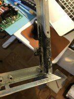
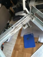
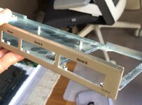
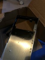
Before reassembling the card cage, I went ahead and cleaned up some corrosion on the bottom plate, and applied some rust converter paint locally to keep it from corroding again. Be careful not to get any paint on the port labels that are just on the other side of that side edge!

IMG_5082.jpgIMG_5098.jpgIMG_5099.jpgIMG_5100.jpg

At this point, I was happy with how the card cage was coming along! Once the paint had dried, I assembled the cage again.

IMG_5128.jpg


The final step before we can try powering on the computer for the first time, is to inspect the PSU for obvious issues. Coming up in the next post!
 
Last edited:

rdmark

Moderator
Staff member
Oct 3, 2021
164
230
43
In part three, we will bust open that PSU to see what's going on inside. We also take a moment to look at the Video Board.

Here it is worth remembering that my friend, the owner of this Lisa, said that he recalled the computer not being quite functional circa 1994: only running for a few minutes maximum before powering itself off. Therefore, I did expect to have to spend some time with the PSU. Computers tend to get worse over time in storage, not better, after all!

The PSU itself lives in a modular metal enclosure behind the back panel of the computer. A large thumbscrew is all that's holding it into place.

IMG_5055.jpg


After removing three Phillips screws on one side, and two on the other side, the case does come open although it might be stuck and stubborn at first. What immediately greets us when inspecting the internals, are three little stink bombs, also known as Rifa caps. Good thing we didn't try to turn this thing on first!

IMG_5058.jpg


I sourced new filter caps for the PSU, settling on blue TDK manufactured ones, rated for 250 VDC / 160 VAC which should be enough for the hot side of a 120 VAC PSU. The values were 1x 0.1 uF, 2x 2200 pF.

IMG_5111.jpg


With the little blue guys in place, and no other obvious sign of damage (fuse intact, no bulging / leaking caps, signs of explosions) I decided it was time to turn it on for the first time! First, I thought a quick test by itself wouldn't hurt. A switching power supply like this should at least not get damaged, but rather not turn on fully. With mains power, I could confirm 5V on the stand-by power rail, but no other activity. At least the new filter caps didn't explode!

Anxious to see what would happen, I quickly put the computer back together, hooked up the power cord.... aaaand [drumrolls].... nothing. Or rather, the moment we plugged the power cord in, we heard the high-pitched whine of what was probably the transformer turning on and off in ~1s intervals.


Here it's worth noting that the fact that the computer tried turning on the moment we connected mains voltage, is a hint of a fault that we will butt heads with a little later. If you're an experienced Lisa repair person, you may know right away what I'm talking about.

A PSU turning itself on and off repeatedly is a telltale sign of overvoltage protection kicking in. I'm not an expert on switching PSU design, but I've repaired a few of them, and by experience know that failure of passive components, in particular shorts, can lead to voltage regulation malfunction. So I decided to embark on the tedious process of testing all passive components one by one.

IMG_5137.jpg


Resistors are a good start. I don't think they short out very often, rather the opposite. But they can be tested in-circuit, so it's a good low-hanging fruit to start with. Busting out my multimeter, I worked through each one of them, noting resistors that had very low resistance, then using a color code lookup table to make sure they were in spec. Which they all were.

Next up, I decided to tackle transistors, since there were only six of them on the board. Testing them in-circuit, two of them tested as dead short on the base to either the emitter or collector. This doesn't necessarily mean they're bad, since f.e. residual voltage from caps could cause this behaviors. This is why transistors (and diodes and caps) need to be tested outside of the circuit. This tutorial was a great crash course on testing transistors!

IMG_5140.jpg


Out of circuit, all transistors ended up testing perfectly fine. I promptly installed them all back in place, and to make sure I hadn't made anything worse, I assembled and powered up the computer again.

And to our surprise, the old girl sputtered to life! What specifically could have triggered this? One thing that springs to mind is one or more cracked solder joints that were rejuvenated through the troubleshooting process.

IMG_5141.jpg


We only got memory garbage on screen and no other sign of the CPU executing code, so she was more undead than truly alive at this point. But it was a start! It should be mentioned that while I was trying to measure voltages on the I/O board in this state, the computer shut itself down after a few minutes, reverting back to the overvoltage protection loop.

At this point, someone at a Lisa Facebook group pointed out this troubleshooting thread which contained a few useful and concrete things to try. Among those, were the fact that the 5V rail adjustment pot, R29, on the PSU tends to get oxidized and trigger rapidly ramping voltage on that rail. (It's visible in the middle right of a previous picture.) Following this lead, I busted out my can of contact cleaner (plastic safe) and sprayed some of it underneath the pot, then twisted it back and forth a dozen times.

I did not have my hopes up, but just in case, put the PSU back in, and connected mains voltage....

IMG_5147.jpg


...it boots!!

Hooray!

The CPU is clearly executing code from ROM at this point, and the Video Board and CRT are displaying a bright and sharp picture. The self check ends with a loud beep and I/O board error 52, so we're clearly dealing with some logic board errors here, but we're at least out of the power supply woodworks! Huge relief!

Before going any further, I decided to give the Video Board a closer inspection.

IMG_5060.jpg


It sits obnoxiously wedged in behind the CRT tube, but unlike first appearances, you can unscrew two screws at the top, and unplug three cables, which allows you to slide the board upwards and out of a socket down below. At this point, it's still connected to the CRT neck board, and I don't have the tools at hand to unscrew the nuts that hold the CRT in place, nor was I willing to desolder the neck board cables, so I decided to work on it on top of the case for now.

The two large 2200 uF 25 V caps seemed suspiciously misshapen so I went ahead and replaced them with fresh low-ESR 105 degrees operating temperature ones. The six adjustment pots were of a similar kind to the one in the PSU, so I worked some contact cleaner into them too, as a precaution.

We end this episode with a mostly working computer, save for that pesky error 52. We will address this error, and then start working on refurbishing the peripherals in the next episode!
 
Last edited:
  • Like
Reactions: warmech

rdmark

Moderator
Staff member
Oct 3, 2021
164
230
43
With the computer now powered and executing ROM code, we were no longer fumbling around in the dark messing with the arcane mysteries of mains voltage! A quick voltage check on one of the ROM chips on the I/O board while the computer was running confirmed a nice and clean 5V.

Luckily, Lisa error codes are well documented, with code 52 mapping to "I/0 COP421 error" where COP421 happens to be a chip that sits conspicuously close to the battery damaged part of the I/O board. Reading up on the COP chip tells us that it among other thing control the soft power circuitry of the computer. If it's malfunctioning, the computer will get powered up the moment it's connected to mains voltage, which was exactly what we observed early on! It also explains why the power button on the front of the computer had no effect. It's apparently a bespoke chip that National Semiconductor manufactured for Apple, and very hard to replace if dead. This was worrying news indeed, but no matter, let's get to the bottom of this!

The first thing that I noticed that COP421 was dead cold during operation, while all surrounding chips warmed up nicely. Looking up the data sheet for COP421 I could confirm that pin 9 is VCC, but my multimeter reported no voltage whatsoever. The chip is not getting powered.

So, back to exploring the traces leading to the COP chip. Testing continuity between all 24 pins and the final test points on top of the board revealed no problems. However, then I remembered that crusty vias could sometimes cause issues, so I started testing continuity to the underside of the board. Initially, I still got continuity everywhere, but then when looking closely at the multimeter screen, I noticed an unexpected resistance on one trace in particular. It was something like 90 Ohm after passing through a via. Looking closely at the via with a loupe revealed a very crusty one indeed.

InkedIMG_5077.jpg


Highlighting a part of a previous shown picture. Note the COP chip to the left there, and the offending via marked in blue to the top right.

At this point, I busted out the fiberglass pencil again for a second go at cleaning up this part of the board. The half-assed solder wick scrubbing from earlier clearly wasn't sufficient!

IMG_5263.jpg


I kept scrubbing until every via and trace had nice copper shine to them. Then applied some protective solder and lacquer on top of that. And what do you know, the resistance observed earlier went away! I'd love for someone who understands the physics involved here how on earth resistance could be "scrubbed away" -- I certainly did not add any conductive material before testing, so why did conductivity improve?

The laws of physics aside, it was time to test if this effort had paid off. The I/O board went back into the card cage, I grabbed the power cord and connected it to the PSU, and... what do you know: the computer did NOT power on! Which was a good sign that the COP chip was in control now. I reached for the power button in the front, and...

IMG_5148.jpg


...it friggin' works! (To borrow Adrian Black's catchphrase.)

Next, in order to load some software, I turned my attention to the 400k Sony floppy drive. Initially, I thought it was dead as a doornail, because when I put my usual 3.5" cleaning disk into it, there was no reaction whatsoever from the mechanism. So for starters, I did some rudimentary cleaning up of dried out lubricant, and added some lithium grease it its stead, and then dripped a little turbine oil into exposed bearings. I couldn't immediately figure out how to disassemble the mechanism further for a more thorough refurbishing. Something for another day!

IMG_5155.jpg


Little did I know that this particular drive apparently does absolutely nothing unless you insert actual magnetic media into it. Once I tried that, the computer booted happily into Lisa Office System (although I quickly learned that Lisa OS software is useless without a hard drive, which this Lisa currently does not have available.)

IMG_5152.jpg


I also tried booting into MacWorks XL to play around with some Mac software.


Ultima II for Mac can be played more or less with the mouse...

IMG_5156.jpg


Lode Runner, however, isn't much fun without a keyboard, so in the next episode I will tackle refurbishing the Lisa keyboard, among another few remaining tune-ups. We're getting very close to a functioning computer now! How exciting.
 
Last edited:

rdmark

Moderator
Staff member
Oct 3, 2021
164
230
43
Despite Steve Job's best efforts in revolutionizing the UI of Apple computers, there are still occasions when you need a keyboard handy while using a Lisa. For instance, when pressing 'Y' to accept the terms and enter the Basic Lisa Utility. :)

As such high up on the priority list at this point is to fix the keyboard! Off the bat, there were two obvious issues with the keyboard. For one, the cable had been all but severed clean through at one location. And secondly, being a foam and foil mechanism, the foam material will with 99.99% certainty have disintegrated after 40 years, rendering the keyboard completely useless.

IMG_5159.jpgIMG_5160.jpg

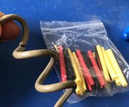
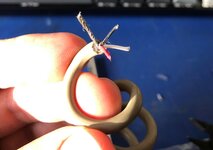
The cable is hanging on by a literal thread here, with only a sliver of plastic keeping it together. Splicing it open reveals three leads, and cable shielding (twisted into shape here by me.)

IMG_5162.jpgIMG_5163.jpg

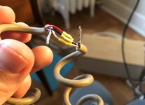
Leads connected and heat shrinks applied. Continuity tests good from the audio-style plug to the header on the keyboard PCB.

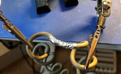
I soldered together the ends of the twisted-up shielding lead as well, and wrapped some aluminum foil around it for the proper back-alley hackjob look. No idea if trying to replicate the shielding like this is advisable or even needed, but it seemed appropriate somehow!

IMG_5182.jpg

Afterwards, I sealed it up with a good length of electrical tape. Some kind of heat shrink solution would be 100% better, but this will probably hold together okay for a little while at least.

Onto dealing with the foam and foil pads!


Let's get these things out of there, using a pick to reach underneath the bottom plastic disk and prying until it pops out. Safety googles is recommended for this job, since they pop out at a surprising velocity at very unpredictable angles!

IMG_5190.jpg


Look at all that gross foamy residue everywhere! Pro tip: One way to test a foam and foil keyboard before you get replacement pads is to take the transparent plastic disk from a deteriorated pad and put it on your fingertip. This turns your finger into a capacitive touch device!

IMG_5217.jpg


With high-quality replacement pads from TexElec in place, the keyboard is ready for testing! Installing new pads can be fiddly. There are four clips on each side of the keycap frame that each must lock into the transparent plastic disk. Again, the pick here comes in handy! You may need to go several rounds to double and triple check all edges.

While I don't have a working Lisa OS environment at the moment, booting into MacWorks XL and using the Finder's Key Caps I could confirm that all keys that are mapped to a Mac keyboard layout are now reacting perfectly well! The only issue observed is that Caps Lock does not actually lock in the OS, although it physically locks on the keyboard. I'm not sure at this point if this is a Mac software incompatibility, or a physical fault with the keyboard. This is something I will revisit once I have Lisa OS up and running.

The final fault to address is that the power button does not light up when the computer is turned on! The most obvious cause would be that the little incandescent bulb in there has burned out after 40 years. Only one way to find out!

IMG_5199.jpg


It turned out to be a bigger pain than expected to get to the assembly that houses the power button and keyboard connector. You have to take off the left side panel, bottom panel, and feet of the Lisa, then reach into a very narrow space and fiddle with two Phillips screws. Then you need to gently pry off the top of the power button with something like a plastic prying tool, careful not to crack the brittle plastic. It's held in by two little clips. Finally, with the bulb free I could inspect it with a loupe and confirm that the lead inside the bulb is indeed torn. Onto sourcing a replacement, which is a 6.3 V 200 mA incandescent bulb with a *wedge* base. I got my replacement one from Mouser.

IMG_5219.jpg


Look how it shines for you! (And everything you do...)

These gentle Yellow bulbs are quite comforting. :)

IMG_5266.jpg


And there you have it! A much more happy Lisa, although currently cosplaying as an Extra Fat Mac with rectangular pixels.

(Note that the mouse is not original, but rather belongs to the Apple //c beside it. The owner of the Lisa does have an original Lisa mouse as well, but it's currently being used as a Mac mouse elsewhere.)

In the next episode we will experiment with making the Lisa a more well-rounded computer. For one, I want to build a Cameo/Aphid hard drive emulator device to replace the long-lost ProFile drive this computer was originally configured with. This way, we can get both Lisa Office System, as well as a hard drive install of Mac System Software set up.

And secondly, I want to try to put together a Lisa Serial B (DB25) to Mac Serial (Mini DIN) cable so that the computer can be networked over AppleTalk.

I'm happy to take suggestions of what else to do with her! Are there any neat peripherals to add, or software to try out?
 
Last edited:

ScutBoy

Administrator
Staff member
Founder
Sep 2, 2021
337
316
63
Northfield, MN USA
I've never been able to get LisatTest to run. I think I have a corrupted disk/image. Do you have a source for what worked for you?
 

rdmark

Moderator
Staff member
Oct 3, 2021
164
230
43
I've never been able to get LisatTest to run. I think I have a corrupted disk/image. Do you have a source for what worked for you?
Yes, if you look closely at my previous comment, I linked to the specific disk image that I used, hosted over at the Mac Repository. I simply loaded this onto my FloppyEmu running in Lisa mode, and it worked without issue on my Lisa.
 

warmech

Tinkerer
Oct 30, 2021
79
101
33
@rdmark I just acquired a Lisa 2 in a near identical state. The COP421 looks like it survived the battery leak unscathed, so I'm hopeful for this thing's future. This thread will be an invaluable repair guide to reference as I get this thing shored up - thank you so very much for documenting your efforts!
 

warmech

Tinkerer
Oct 30, 2021
79
101
33
@rdmark Would you happen to have a BOM or list of vendors you got ICs from? Figured I'd ask here first rather than just duplicate work that may already have been done.
 

rdmark

Moderator
Staff member
Oct 3, 2021
164
230
43
@rdmark Would you happen to have a BOM or list of vendors you got ICs from? Figured I'd ask here first rather than just duplicate work that may already have been done.
I didn't replace too many parts to be honest. Looking at my Mouser order history, here are the relevant components that I can note:
One of the key components to repair the Motherboard, the Bourne 20 pin 200 Ohm EMI Filter IC is no longer available from Mouser, unfortunately. It was clearly marked as EOL when I ordered it, so not surprising.

Also, see an earlier post for a link to the eBay seller that carries those 120 pin sockets for the Motherboard...

I also replaced a few resistors and electrolytic caps that were in poor shape as I went along, but the parts came out of my stash so I didn't keep a record. Sorry!
 

warmech

Tinkerer
Oct 30, 2021
79
101
33
I didn't replace too many parts to be honest. Looking at my Mouser order history, here are the relevant components that I can note:
One of the key components to repair the Motherboard, the Bourne 20 pin 200 Ohm EMI Filter IC is no longer available from Mouser, unfortunately. It was clearly marked as EOL when I ordered it, so not surprising.

Also, see an earlier post for a link to the eBay seller that carries those 120 pin sockets for the Motherboard...

I also replaced a few resistors and electrolytic caps that were in poor shape as I went along, but the parts came out of my stash so I didn't keep a record. Sorry!
Thanks! I picked up a replacement card edge connecter from your eBay link above and picked up some ICs from Mouser to replace ones that at least look toasted, so I should be good there. I had to order the EMI filters from DigiKey, as Mouser is now totally out of them, so no big deal there thankfully. I'll have to order some other passives to replace components in affected areas, but it shouldn't need many. No worries on not having a full tally - I just wanted to make sure I wasn't missing something obscure more than anything else.

Tangent question, though - if I remove the two EMI filters and leave the I/O board disconnected, will the unit still power on (automatically, I would assume) when power is attached? Or will the absence of the I/O board stop it dead in its tracks? I'd like to test to see if it at least powers on in its current state. For what it's worth, the motherboard had very little damage, and almost all of it was was relegated to the I/O connector (which I have since removed - what a paint that was, lol).

EDIT: Would you (or anyone) happen to have a set of schematics for the motherboard as well? Mine isn't in rough shape, but I can't find them anywhere in order to double check...
 
Last edited:

rdmark

Moderator
Staff member
Oct 3, 2021
164
230
43
Tangent question, though - if I remove the two EMI filters and leave the I/O board disconnected, will the unit still power on (automatically, I would assume) when power is attached? Or will the absence of the I/O board stop it dead in its tracks? I'd like to test to see if it at least powers on in its current state. For what it's worth, the motherboard had very little damage, and almost all of it was was relegated to the I/O connector (which I have since removed - what a paint that was, lol).

EDIT: Would you (or anyone) happen to have a set of schematics for the motherboard as well? Mine isn't in rough shape, but I can't find them anywhere in order to double check...
I tried running my Lisa without the I/O board. It started up (automatically, as you guessed) and soon hits error 41. But there is code executed at least, and an error displayed on screen.

As for Motherboard schematics, I've also not found easy to read reference material. I think parts of the Motherboard circuitry are folded into the schematics for other boards.
 

warmech

Tinkerer
Oct 30, 2021
79
101
33
I tried running my Lisa without the I/O board. It started up (automatically, as you guessed) and soon hits error 41. But there is code executed at least, and an error displayed on screen.

As for Motherboard schematics, I've also not found easy to read reference material. I think parts of the Motherboard circuitry are folded into the schematics for other boards.
Good to know it can "boot" to some some extent for testing. That alone will provide a world of info moving forward - thanks!

As far as it being spread across other schematics, I think you're right. I may sit down and tone out the motherboard before I do anything further. I've got both EMI filters removed (they were corroded to hell and back) as well as the two serial ports off (multiple pins on each were just roached) and the PCB is nice and clean; now would probably be the best time to take a look at that. There are three lifted pads for the I/O connector and two on the EMI filters, so I'll have to figure those out anyway in addition to any broken traces. If I run into some traces that look off, might I be able to ask you to tone out some connections on your board?
 

rdmark

Moderator
Staff member
Oct 3, 2021
164
230
43
Good to know it can "boot" to some some extent for testing. That alone will provide a world of info moving forward - thanks!

As far as it being spread across other schematics, I think you're right. I may sit down and tone out the motherboard before I do anything further. I've got both EMI filters removed (they were corroded to hell and back) as well as the two serial ports off (multiple pins on each were just roached) and the PCB is nice and clean; now would probably be the best time to take a look at that. There are three lifted pads for the I/O connector and two on the EMI filters, so I'll have to figure those out anyway in addition to any broken traces. If I run into some traces that look off, might I be able to ask you to tone out some connections on your board?
If the traces can be followed from the top of the PBC I can help out at any time! If I need to disassemble the card cage to get to the underside of the PCB, I might ask you to batch your requests since it's fairly cumbersome to pull apart.

Full disclosure: After using this Lisa actively for a few weeks after I repaired it, it developed a consistent Bus Error fault while loading data from the floppy interface, which makes it impossible to boot into any software at the moment. It's one of those obnoxious faults that isn't caught by the self test. The current running theory is that the MMU isn't getting valid data, or data delivered too late, from the floppy controller, probably caused by a failed or marginal logic chip somewhere on that circuitry.

Anyhow, all this to say that the repair story of this Lisa has not yet ended.