Mac IIcx no chime after board re-cap and startup circuit repair

kris

New Tinkerer
Feb 2, 2022
13
6
3
Hi All,

Trying to coax a IIcx back to life and figured I'm come to the group if anyone has any suggestion.

For some background, this machine had an extreme case of leaky capacitors with corrosion mainly focused in the area of the startup circuit. After an initial recap of the entire board, the machine was basically dead. For additional context, the power switch on the board activated the PSU, but that was it, couldn't even turn the machine off without directly pulling the plug.

From there I started digging into the schematics and unsurprisingly found a slew of broken traces in the startup circuit area. I ended up lifting every chip, cleaning under the board and fixing every trace and pad that was barely hanging on. After hand-wiring at least half of the connections for the mux chips and ram address lines, still no chime, but perhaps marginal success in that the startup circuit now appeared to be functioning correctly (I can turn the machine on and off with the switch and soft power works as well).

Moving on from that area of the board, I went to known culprits for this family of machines; Checked the sony sound chips. Continuity was there on the reset lines and other connections. One chip had a little oxidation so I lifted it to see if anything underneath needed attention, but it was fine, so I just cleaned everything and slapped it back on.

Additionally, I've tried to rule out the dumb stuff too: Swapped known good PSU from a IIci that I have. Tested RAM in other machines, swapped RAM from working machines, PRAM battery, etc. Heck I even dropped in an SE/30 and BMOW ROM SIMM to bypass the onboard ROM. Still no change in result.

I get power on, the speaker/headphone pops with power/reset, but thats about it. I was figuring with the address lines connected again, I'd at least get a death chime to try and investigate any other errors that might exist. Can you expect power on/off to 'work' and nothing else happen if one of these logic chips are bad?

So here I am now, sort of just guessing, and I'm hoping that someone may have encountered this or something similar with a IIcx and could offer any suggestions. I have also admit that I'm sort of limited with equipment for further chip-level testing at the moment with the lack of an oscilloscope, but maybe there's something else that I'm just overlooking to try and advance this thing a little further. Any recommendations are much appreciated.

TL;DR:
  • Recapped the board
  • Thorough cleaning
  • Re-wired startup circuit
  • Corrected other obvious spots
  • Machine still dead. Need help. Thank you in advance.

-Kris

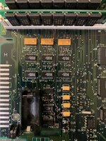
If anyone's curious, attached is the repair on the area for the startup circuit/RAM/ROM line.
 

Attachments

  • 24-02-27 11-47-06 2966.jpg
    24-02-27 11-47-06 2966.jpg
    2.1 MB · Views: 81
  • Like
Reactions: DevyDevly

Kai Robinson

TinkerDifferent Board President 2023
Staff member
Founder
Sep 2, 2021
1,206
1
1,203
113
42
Worthing, UK
I wonder if a IIcx reloaded from @max1zzz might be the best place to start with now that you've gone through the exhaustive process of recapping and rewiring everything.
 

kris

New Tinkerer
Feb 2, 2022
13
6
3
Yeah, I figured if I can't get it working, a reloaded board would probably be in my future. I was optimistic about resurrecting this one because the board doesn't look bad at all. Certainly looks can be deceiving though. I guess before I go that route, I'd like to rule out any bad chips, because I'd potentially be in the same boat. Any pointers on where to start probing in the startup sequence for the IIcx, or should I just start dividing the board into sections and then checking for continuity against the schematics again. I guess on a positive note Ive already done it for one section. Surely if theres a break somewhere it will expose itself.
 

cesare

New Tinkerer
Apr 6, 2024
5
3
3
Just wondering if you got anywhere with your IIcx? I've got one which was working, then working intermittently, now appears to never get as far as a chime and i'm just about to dig in with some bus analysis to see if it's obvious where it's failing...
 

kris

New Tinkerer
Feb 2, 2022
13
6
3
Just wondering if you got anywhere with your IIcx? I've got one which was working, then working intermittently, now appears to never get as far as a chime and i'm just about to dig in with some bus analysis to see if it's obvious where it's failing...
Unfortunately I haven't. Still on my workbench and I come back to it every so often. I sort of resorted to toning out traces in sections and touched up a few areas while crossing my fingers. I plan to get my hands on a scope and pick this project back up soon though. Curious as to what you may find out on your bus analysis. Please keep me posted.
 

phipli

Tinkerer
Sep 23, 2021
250
179
43
Folks, have you had a look in the "Guide to Macintosh Hardware 2nd Edition" book? Its available online as a pdf. Specifically, there is an interesting bit from page 269 (pdf page 308 - linked here). This section gives some clues for some things to check for.

This is a block diagram (representing the II, IIx and IIfx, but the IIcx is similar (although not identical). The obvious difference is that the other machines take a 5v trickle from the PSU instead of from dual batteries).

1736086932109.png


If you're using the bomarc schematic, you might find the Max's gerbers in a gerber viewer a much better bet - the bomarc schematics are a nightmare to read. Also, try Apple's IIci schematics as the power circuit is pretty similar and they're generally easier to read.

This is the power circuit from the IIci schematic, sadly it has been cropped at some point in the past, but may still be useful. Obviously the chip designations will be different.

1736088053251.png


I get power on, the speaker/headphone pops with power/reset, but thats about it. I was figuring with the address lines connected again, I'd at least get a death chime to try and investigate any other errors that might exist. Can you expect power on/off to 'work' and nothing else happen if one of these logic chips are bad?
My first suspicion would be the ROM address lines - the area you've already had trouble with - it is near the battery and a load of caps. The speaker pop means the sound chip is being reset, but it doesn't sound like you're getting much further than that. Does the CPU get warm? Does the RAM get warm?

Check the Clocks are outputting something / anything at all. Perhaps stick a meter set to measure voltage on the output pin of the various clocks and see if they report a voltage between 0 and 5v (that isn't zero).

One thing to check is that you haven't repaired something that didn't need repairing - I've had boards turn up here where someone had repaired... erm... extra stuff that wasn't connected originally. That was stopping the board working.

I wonder if a IIcx reloaded from @max1zzz might be the best place to start with now that you've gone through the exhaustive process of recapping and rewiring everything.
To a degree I'd only recommend that if there was a known difficult or impossible to fix issue. Without lots of PCB assembly experience and bloody-mindedness, you'd just be trading finding broken traces and dry joints for finding solder bridges, dry joins and overheated recovered components. Its cool that it exists, but it really is generally easier to fix a corroded board than start from scratch! Plus you might end up carrying the bad component over anyway :ROFLMAO:

Just wondering if you got anywhere with your IIcx? I've got one which was working, then working intermittently, now appears to never get as far as a chime and i'm just about to dig in with some bus analysis to see if it's obvious where it's failing...
Daft question, but have you recapped it (logic board and PSU)? Have you tried another known good PSU? This sounds like it might be a PSU issue.
I'm interested in any developments here as I'm in the same boat'
I've rebuilt the badly damaged startup circuit on my IIcx and recapped. I can now get it to power on but it doesn't seem to even try booting.
See https://68kmla.org/bb/index.php?threads/restoring-my-iicx.48705 for details of my progress.
You're lucky the battery goop went the direction it did, away from the important stuff. BTW, one issue with 68kmla is that they only let you view images if you're logged in, so it is probably worth reposting them so people can look at them in detail.

Reading through your thread, I'd just recommend keeping inspecting the area around the battery damage, paying particular attention to the lines that go to the ROM (there is one that goes right under the battery if I remember). Beep out the address lines - do they go where they should?
 
Last edited:

rodders

New Tinkerer
Jan 4, 2025
33
4
8
You're lucky the battery goop went the direction it did, away from the important stuff. BTW, one issue with 68kmla is that they only let you view images if you're logged in, so it is probably worth reposting them so people can look at them in detail.
Here are a few of images to give an idea of what I faced.
This is what the machine looked like when I got it
As Bought.jpg
And this was the battery damage I found. Luckily it looks like the machine was stored on its side, minimising the damage.
Battery Damage.jpg
This is after my repair attempts, the power is starting up OK now.
Startup Repaired.jpg
(Tricky uploading images on this site, I kept getting Parsing Response Failed errors)
Beep out the address lines - do they go where they should?
Funnily enough I was just preparing a list of buzz points to check out the data and address buses. I'll post anything I find.
This is the power circuit from the IIci schematic,
I found this startup schematic for the IIcx which I found useful
IIcx Startup Circuit.png
 
  • Like
Reactions: DevyDevly

rodders

New Tinkerer
Jan 4, 2025
33
4
8
Hmm, Address and Data buses between CPU and ROM all buzz out OK.
The first thing that happens on reset is for the CPU to get the Reset Vector from address $0. I'm struggling to find where this comes from. It can't be in ROM as they don't have address lines A0 and A1. Does it come from the GLUE chip?
I'll put a scope on the data bus and see if I can capture some activity when the rest vector is accessed.
 

phipli

Tinkerer
Sep 23, 2021
250
179
43
Hmm, Address and Data buses between CPU and ROM all buzz out OK.
The first thing that happens on reset is for the CPU to get the Reset Vector from address $0. I'm struggling to find where this comes from. It can't be in ROM as they don't have address lines A0 and A1. Does it come from the GLUE chip?
I'll put a scope on the data bus and see if I can capture some activity when the rest vector is accessed.
Page 282 onwards here might help : https://vintageapple.org/inside_o/p...Family_Hardware_2nd_Edition_1990.pdf#page=282

I suspect address lines A0 and A1 aren't connected because the ROM is 32bit and the addresses are in bytes? Or am I being daft? So basically, you don't need the resolution of A0 (8bits) and A1 (16bits) because they're captured within a single 32bit word? Edit - I.e. A0 and A1 are implicitly 0 at all times.

The thing that might trip you is that initially ROM is mapped (overlaid in fact - so actually duplicated and replaces some of RAM) to address 0, but one of the first things the code at 0 does is jump to the real ROM location ($4000 000) and tell VIA1 turn off the overlay using the memory control IC. This is something to check for - does the VIA1 pin change state as expected and does execution jump to somewhere at $4000 000 or above. The VIA1 overlay pin should initially be high... need to check which pin... PA4, which is pin 6 on chip UK6?? Forgive me if I have that muddled.
 
Last edited:

rodders

New Tinkerer
Jan 4, 2025
33
4
8
I suspect address lines A0 and A1 aren't connected because the ROM is 32bit and the addresses are in bytes? Or am I being daft? So basically, you don't need the resolution of A0 (8bits) and A1 (16bits) because they're captured within a single 32bit word? Edit - I.e. A0 and A1 are implicitly 0 at all times.
Of course you are right, its handling 32bit words so A0 and A1 aren't needed (always 0)
The VIA1 overlay pin should initially be high... need to check which pin... PA4, which is pin 6 on chip UK6?? Forgive me if I have that muddled.
I was trying to track that down. It is UK6 pin 6 connecting to UK13 (GLU) pin 49. I'll check for continuity and then put the scope on it.
 

phipli

Tinkerer
Sep 23, 2021
250
179
43
Of course you are right, its handling 32bit words so A0 and A1 aren't needed (always 0)

I was trying to track that down. It is UK6 pin 6 connecting to UK13 (GLU) pin 49. I'll check for continuity and then put the scope on it.
It will only switch once, so a meter would be fine for checking it if you can get a safe connection. There will be a test point I'd suspect. I'll see if I can find what it is for you... (I'll edit it in if I find it, if I don't, assume I couldn't or got distracted by a passing bee).
 

rodders

New Tinkerer
Jan 4, 2025
33
4
8
Well the Overlay line has continuity but I can't see any activation on it. It goes high on switch on and stays there.
Scoping the address and data buses shows no activity at all.
I've probed the CPU (not buses) and every pin is high except E1 CLK (shows a ragged sine wave), C1 FC1, E2 AVEC, J12 STATUS, L2 SIZ0, L3 R/W and M1 DBEN are low. Some pins show 1.5V which is odd.
I need to have a good look at the 68030 datasheet!
The original PSU had a blown Rifa capacitor and I'm wondering if this has fried the CPU. I hope not.
 
Last edited:

phipli

Tinkerer
Sep 23, 2021
250
179
43
Well the Overlay line has continuity but I can't see any activation on it. It goes high on switch on and stays there.
Scoping the address and data buses shows no activity at all.
I've probed the CPU (not buses) and every pin is high except E1 CLK (shows a ragged sine wave), E2 AVEC, J12 STATUS, L2 SIZ0, L3 R/W and M1 DBEN are low. Some pins show 1.5V which is odd.
I need to have a good look at the 68030 datasheet!
The original PSU had a blown Rifa capacitor and I'm wondering if this has fried the CPU. I hope not.
OK, that means the CPU isn't running code from the ROM, that is a big clue.

Rifa shouldn't have done any harm to the logic board. They generally either cause no actual visible functional change or blow the fuse in the power plug.
 

rodders

New Tinkerer
Jan 4, 2025
33
4
8
16MHz 68030 chips seem scarce, anyone know if a higher rated one (e.g. 25MHz) can be used?
 

rodders

New Tinkerer
Jan 4, 2025
33
4
8
Unfortunately mine isn't socketed so its going to be a pig to get out. 128 pin PGA sockets seem like hen's teeth (or extremely expensive) too.
 

phipli

Tinkerer
Sep 23, 2021
250
179
43
Unfortunately mine isn't socketed so its going to be a pig to get out. 128 pin PGA sockets seem like hen's teeth (or extremely expensive) too.
Sorry, just realised I did a thing I do. I answered your question and didn't think about the context.

It is very unlikely to be the CPU. It almost absolutely never is.

I would still be checking traces and even perhaps check the ROM contents are valid.
 

phipli

Tinkerer
Sep 23, 2021
250
179
43
Also, use a scalpel to ping (gently nudge) each pin on QFP chips to check that there aren't any dry contacts. If they wiggle, resolder them. That's where a lot of issues can be found. Especially on plug in cards, but on corrosion damaged boards too. The pain is that if you put a probe on the pin, you push down and get good contact, so they can be hard to find any way other than visually.

Another issue I've had is corrosion cutting pads right where the trace connects to a pad, it is almost invisible.

For finding bad traces, photograph the board and draw a grid over it, then visually inspect each square of the grid obsessively. Mark them off as you finish looking at every single pad and trace in each square and move to the next. It helps make sure you have looked at everything. I tend to have most luck finding faults visually, but it is hard to... actually make yourself look everywhere!
 
  • Like
Reactions: DevyDevly

rodders

New Tinkerer
Jan 4, 2025
33
4
8
It is very unlikely to be the CPU. It almost absolutely never is.
Well that's a relief.

Also, use a scalpel to ping (gently nudge) each pin on QFP chips to check that there aren't any dry contacts. If they wiggle, resolder them. That's where a lot of issues can be found. Especially on plug in cards, but on corrosion damaged boards too. The pain is that if you put a probe on the pin, you push down and get good contact, so they can be hard to find any way other than visually.
Thanks for the tip, I'll try the scalpel test although I do try to buzz test on the pins without much pressure.
Another issue I've had is corrosion cutting pads right where the trace connects to a pad, it is almost invisible.
Yes, I've had that too on an Acorn A3020 (battery leakage)
For finding bad traces, photograph the board and draw a grid over it, then visually inspect each square of the grid obsessively. Mark them off as you finish looking at every single pad and trace in each square and move to the next. It helps make sure you have looked at everything. I tend to have most luck finding faults visually, but it is hard to... actually make yourself look everywhere!
Another great tip. Its easy to get distracted though and miss something.
I'm trying to put together more buzz lists but its tricky to get everything and I'm not 100% confident with the Bomark schematics.