Hello all,
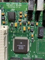
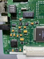
I'm working on a particularly unhappy Macintosh IIci board. After a recap and repair of the startup circuit area, the system turns on (with a green LED on the board), but I don't get a chime. The speaker does "pop". I'm using known-good RAM and the PSU is good as well.
When I turn the system on I get a blank screen, but I do get a colorful (often pink or yellow) flash on the screen once I press the Reset switch on the board.
Oddly enough, the system acts the same whether RAM is installed or not!
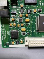
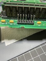
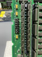
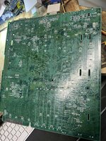
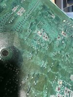
Sadly, the bottom of the board (see attached photos) has a LOT going on, although most of the traces appear to map out okay, I'm sure there could be a problem.... somewhere...!
Here's what I've tried:
- Using a ROM SIMM to bypass the built in ROM
- Swapped the three chips by the startup circuit with new chips
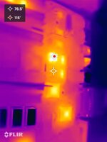
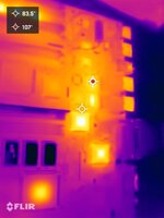
- Looking at the board with a thermal camera (nothing stands out)
- Reflowing the ROM pins under the board
- Reflowing the PSU connector under the board
- Cleaning up around the sound chip
- Cleaning up around the startup circuitry
- An ultrasonic bath
Any ideas of chips / areas to pin out or further troubleshooting paths would be great, thanks!")
-Steve
I'm working on a particularly unhappy Macintosh IIci board. After a recap and repair of the startup circuit area, the system turns on (with a green LED on the board), but I don't get a chime. The speaker does "pop". I'm using known-good RAM and the PSU is good as well.
When I turn the system on I get a blank screen, but I do get a colorful (often pink or yellow) flash on the screen once I press the Reset switch on the board.
Oddly enough, the system acts the same whether RAM is installed or not!
Sadly, the bottom of the board (see attached photos) has a LOT going on, although most of the traces appear to map out okay, I'm sure there could be a problem.... somewhere...!
Here's what I've tried:
- Using a ROM SIMM to bypass the built in ROM
- Swapped the three chips by the startup circuit with new chips
- Looking at the board with a thermal camera (nothing stands out)
- Reflowing the ROM pins under the board
- Reflowing the PSU connector under the board
- Cleaning up around the sound chip
- Cleaning up around the startup circuitry
- An ultrasonic bath
Any ideas of chips / areas to pin out or further troubleshooting paths would be great, thanks!
-Steve
Attachments
Last edited: