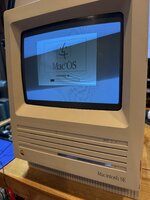
Macintosh SE Checkerboard pattern with random speckled dashes, no boot chime

litriSE

New Tinkerer
Jul 4, 2026
4
1
3
I have a Macintosh SE 820-0176-B, 1986, 630-4125 logic board that shows a checkerboard pattern with random noise/static (speckled dashes) displayed on boot, with no audio boot chime — just a single speaker click. I've installed the suspect board into a known-good SE chassis (proven analog board, PSU, and BlueSCSI), so the fault stays with the logic board regardless of chassis. I'm running 4MB of RAM (4 SIMMs), and I've confirmed this isn't a RAM issue — I've swapped in multiple different sets of tested, known-good SIMMs (different brands/batches) and get the identical noisy checkerboard every time, including after moving all 4 SIMMs into different physical slots.

The board is very clean — I've inspected the RAM sockets, solder joints, and surrounding traces closely and everything looks great, no visible cracks or corrosion. I've tested the ROM, IWM, and SIMM sockets for continuity from installed component pin to trace all good. In addition, I've begun the arduous task of testing nets - nothing so far.

Given the fault is consistent across all SIMM combinations/positions and isn't chassis-related, I suspect it may be in shared RAM-adjacent logic (GLU chip 341-0538-A, ROM chips, or the BBU.. etc. ) rather than the RAM itself. I verified that ROM HIGH - chip 342-0352-A. ROM LOW - chip 342-0353-A, IWM - chip 34-0043A are in the correct slots and oriented correctly in their sockets. All pins are clean and sockets are clean. I have a known good board and swapped out good ROMs and IWM and still the same problem on the troubled board. The swapped good ROMs and IWM still produce checkerboard & noisy lines on the troubled board. The problem still persists.

Has anyone run into this specific noisy/speckled checkerboard symptom before, and if so, what ended up being the fix?

Thanks, litriSE
 

Attachments
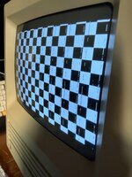
  • 100910-59dca33f4384d0ca1f0abbd95db1efd8.jpg
    100910-59dca33f4384d0ca1f0abbd95db1efd8.jpg
    9.2 KB · Views: 10
Last edited:

litriSE

New Tinkerer
Jul 4, 2026
4
1
3
Update: Macintosh SE checkerboard/noise — continuity testing complete, need advice on scope approach or component swapping


Following up on my earlier post about a Macintosh SE 820-0176-B (1986, 630-4125) logic board showing a checkerboard pattern with random noise/static (speckled dashes) on boot, no chime, just a single speaker click.


Ruled out so far:


  • RAM/SIMMs — multiple tested, known-good SIMM sets (different brands/batches), moved across all four physical slots, identical noisy checkerboard every time.
  • Chassis/analog board/PSU — suspect logic board tested in a known-good SE chassis (proven analog board, PSU, BlueSCSI); fault stays with the logic board.
  • ROM/IWM — verified correct chip placement and orientation (342-0352-A, 342-0353-A, 344-0043A), all pins/sockets clean. Also swapped in known-good ROM HIGH/LOW and IWM chips from my reference board — problem persists unchanged.
  • RAM-size configuration — populated only bank 1 with a soldered 150Ω resistor at R36 to force a clean 2MB config; same noisy checkerboard.
  • Caps — fully recapped the board as a precaution; no change in behavior before/after.
  • Trace/via integrity — completed methodical continuity testing across RA0F–RA9F, RAS1F/RAS2F, CAS0L/CAS1L/CAS0H/CAS1H, and RDO0–RDO15 (LS245 data path) between the 68000/BBU, F257 address muxes, and SIMM sockets, cross-checked against my known-good reference board at the same test points. All continuity confirmed clean and consistent between both boards — no cracked traces or vias found.

Remaining suspects (most soldered direct): GLU (341-0538-A), the two F257 address muxes, the two LS245 data buffers, the BBU (socketed), the 68000 CPU itself, and the VIA. I do have spare pulls for the 68000 and VIA from a donor board if that's useful.


Since the wiring itself now checks out clean on both boards, I believe the fault has to be a chip producing corrupted output despite sound connections — not a broken trace.


What I'm looking for:


  1. Oscilloscope approach — which signals would you prioritize probing first (RAS/CAS timing, F257 outputs, LS245 outputs, BBU outputs) to isolate a marginal/failing chip without needing to desolder blind?
  2. Component-swap priority — if you were choosing which of the six remaining soldered suspects to desolder and replace first, in what order, and why?

Has anyone dealt with this specific "noisy/speckled checkerboard, survives every RAM/ROM/IWM swap and full continuity check" symptom before? Any insight on narrowing it down further would be hugely appreciated.


Thanks,
litriSE
 
Last edited:

litriSE

New Tinkerer
Jul 4, 2026
4
1
3
Update: RESET/HALT stuck low regardless of switch state — chasing what's actively driving it


A fellow member, GreenBarOn, suggested checking whether the Reset and Programmer buttons on the logic board were operating correctly. That question ended up cracking this open.


Step 1: Tested the switches directly.


  • SW1 (interrupt/programmer switch) works exactly as expected — IPL2 sits at a clean 5.12V at rest, and drops cleanly to 0V when pressed. Confirms the general switch/pull-up mechanism on this board is sound.
  • SW2 (reset switch) has zero effect — pressing it or leaving it alone, no change at all downstream.
  • Also found something odd early on: measuring across the open reset switch gave 75Ω on the troubled board, versus 260Ω on my known-good reference board. That was the first hint something wasn't right on this net.

Step 2: Checked CPU control-pin voltages and clock.


  • CLK (pin 15): clean 7.81MHz, ~5V swing — matches the expected 15.6672MHz crystal ÷ 2. CPU has a valid, healthy clock.
  • DTACK, BGACK, BR, BERR, IPL0-2, VCC: all a clean 5.12V.
  • GND, HALT, RESET: all sitting at 120-200mV — essentially stuck low.
  • Power-off continuity check from 68000 pins 17/18 to ground: open, no continuity — so this isn't a dead short or bad solder joint. It's being actively held low under power, not passively shorted.

Step 3: Confirmed switch state doesn't matter at all.
No matter what's done to SW1 or SW2, RESET and HALT stay pinned at 0V. Since SW1's own circuit (IPL2) behaves perfectly on its own switch, this rules out a generic "switches are broken" explanation — something else entirely is holding this specific shared net down, independent of the reset switch.


Where that's led so far:
Traced RST's fan-out via the Bomarc SE schematic (sheet 3 of 4) — it connects to the SND chip (343-0045-B) pin 5 and VIA pin 34, plus the reset switch/pull-up circuit (R12, C28, and a mystery component labeled "PART OF B2"). Tried the known SE/30 fix of jumpering SND pins 7-to-15 with a 1kΩ ohm resistor (documented elsewhere as a fix for "reset signals generated endlessly" on this exact chip) — no change. Confirmed SND pin 5 is a schematic-documented input, so it's just receiving the bad signal, not the source.


Board was fully recapped earlier in this process, no change in behavior before/after, so electrolytics are ruled out entirely.


Still hunting: whatever is actively driving RST low. Leading suspects are the unidentified "PART OF B2" component near the reset switch, or the VIA's RST pin if it turns out to be an output rather than an input. Does anyone know what "B2" refers to as a physical component, or whether VIA pin 34 (RST) is input or output on the R65C22?


Thanks,
litriSE
 
  • Like
Reactions: GreenBar0n

GreenBar0n

Tinkerer
Dec 22, 2025
106
66
28
East Bay Area, CA
Glad to hear you've found the symptom. As far as the cause, I don't think I've ever heard of a Sound chip going bad without being corroded for one reason or another, but it's my understanding that if the actual Reset button is operating correctly, the Sound chip is ultimately responsible for holding the Reset line low. Theoretically, if you were to disconnect the Sound chip Reset line from the Logic Board, would the disconnected Reset pin show the Reset line is being released?
 

GreenBar0n

Tinkerer
Dec 22, 2025
106
66
28
East Bay Area, CA
I have a pair of SE's, but they both have always worked well, I've not needed to work on those; but my SE/30's taught me that it's the Sound chip that releases the Reset line and drives the entire Reset circuit to 5v. Hoping someone else more familiar with the SE can fill in the details for us.