Mystic Died. Looking for an MC88916DW80 chip.

YMK

Active Tinkerer
Nov 8, 2021
358
285
63
But that cannot be right because Zo will change according to the 2X_Q output clock frequency!

Why would Z0 change by frequency? It's the characteristic impedance of the trace.
 

JDW

Administrator
Staff member
Founder
Sep 2, 2021
1,577
1,373
113
53
Japan
youtube.com
@YMK thank you for your kindness in replying, and I appreciate that observation. The answer is this...

1709105373086.png


source: https://resources.ema-eda.com/home/2023-design-recommendations-for-pcb-impedance-control

But let's ignore that for now and assume a fixed Zo impedance that never changes. How do we explain what Apple wrote on the schematic with regard to Rp values?

1709105442577.png


You've somehow got 121Ω for 20-25MHz, then it jumps to 140Ω for 33MHz, but then it drops to 110Ω for 40MHz.

Would you have any idea about that?
 

YMK

Active Tinkerer
Nov 8, 2021
358
285
63
But let's ignore that for now and assume a fixed Zo impedance that never changes. How do we explain what Apple wrote on the schematic with regard to Rp values?

I'm guessing a lot of it has to do with the combination of amplitude and phase at the destination, since reflections affect both.

Apple probably arrived at those values after plenty of component swapping, trial and error.

Even scope lead capacitance can skew the clock enough to make or break operation.
 

trag

Tinkerer
Oct 25, 2021
280
133
43
Why would Z0 change by frequency? It's the characteristic impedance of the trace.

I'm speaking from 20+ year-old knowledge, but the traces have small capacitances to neighboring traces and ground/power planes. Small because they distances are relatively huge. Even a straight conductor has inherent inductance.

Zc = 1/j2(pi)fC; ZL = j2(pi)fL

As the frequecy varies, so too do impedance of the capacitance and the inductance.

But it seems to me that the R of the Zo trace should be well under 10 ohms and that the Zc and ZL should be less than that because C and L will be so tiny. But I'm guessing.

Your suggestion of empirical methods seems likely. Otherwise Rs would vary with frequency adn it does not. Or Rp would not vary with frequency and it does.

Also, looked up some typical dimensions. Traces on 1 oz. copper are .0035cm thick. 6 mil traces are .015 CM wide. Copper resistivity is 1.7 X 10^-6 ohm-cm. Assume a trace length of 2" = 5 cm, which seems kind of long. I would assume that the clock buffer is near the CPU, but I'm guessing.

Anyway, R = L X Resistivity / (T X W) = ~.16 ohms.

So the trace between the 88916 and the CPU should have a resistance well under 1 ohm. Is there really enough C or L in a straight trace to get the impedance up to 70 or 100 ohms?
 
Last edited:

YMK

Active Tinkerer
Nov 8, 2021
358
285
63
As the frequecy varies, so to do impedance of the capacitance and the inductance.

Right, that makes sense. For practical purposes though, doesn't the impedance virtually flatten above 1MHz?
 
Last edited:

trag

Tinkerer
Oct 25, 2021
280
133
43
Right, that makes sense. For practical purposes though, doesn't the impedance virtually flatten above 1MHz?


Well, the inductive impedance is in series between the 88916 and the CPU and it should just keep getting larger as frequency increases, but, despite the danger of guessing without data, I just can't believe the inductance in a straight wire is substantial, even if it has a few bends.

The capacitive impedance in this case is like another ground or VCC connection. One terminal of the notional capacitor is on the trace between the 88916 and hte CPU. The other terminal of the "capacitor" is connected to Vcc or Gnd (neighboring plane) or to the next trace over, which is really fun. Sometimes they run GND traces on either side of CLK traces, to remove the unknown.

Anyway, as the frequency increases, the impedance from these "capacitors" decrease creating a lower and lower resistance between the clock trace and whatever is nearby.

This could be bad, but the capacitance between trace and layer at those macroscopic distance is just going to be tiny tiny. Plus the mu or whatever of the FR4 plays a part as well. OR is it epsilon...

Found a handy on-line self-inductance calculator and it tells me about 75 nano Henries for a 5 CM trace, but the calculator was for a round wire and I calculated an equivalent diameter based on our width and thickness. If that's right, 2 pi f L => ~ j16 ohms impedance at 33 Mhz.

Or I could be wildly wrong. It's been a long time since EE 338K
 
Last edited:
  • Like
Reactions: YMK

JDW

Administrator
Staff member
Founder
Sep 2, 2021
1,577
1,373
113
53
Japan
youtube.com
Sometimes they run GND traces on either side of CLK traces, to remove the unknown.
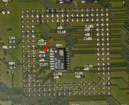
You can see that in my photo here...

1709108083291.png


In the above photo, 88916 chip Pin-8 is the SYNC input, 3rd pad from the right. Pin-9 is Ground. Note how the GND from Pin-9 loops around the Pin-8 trace.
 
  • Like
Reactions: YMK

JDW

Administrator
Staff member
Founder
Sep 2, 2021
1,577
1,373
113
53
Japan
youtube.com
Well, I did further testing this evening, at the stock clock speed of 33MHz with the 8MB universal ROM SIMM that @Jockelill helped to create, and I provided him some feedback. (Basically, it works to kill the painfully slow RAM checking at cold boot, but booting from ROM still has bugs that need to be worked out.)

After that, I reinstalled Spicy O'Clock, testing with a low clock speed setting of 39MHz. I was able to boot into the following OS's just fine:
  1. System 7.1
  2. System 7.5.5
  3. System 7.6.1
  4. OS 8.1
I then boosted the clock speed to 43.2MHz, which is right at the very edge of serial port operation. (I know from past testing that the serial ports stop working at 43.7MHz.) Again, I was able to boot all the above OS's just fine.

By the way, I am doing all this testing today with the internal spinning platter HDD disconnected, booting from an externally connected BlueSCSI v2. The reason why is because the Universal ROM SIMM has some bugs with spinning platter drives, so to avoid that, I used only BSv2.

I'm out of time this evening, so tomorrow I will reinstall my Apple IIe Card, reconnect the small 40mm fan, then test again. I will also do an overnight test using MacBench 3.0 because it takes a very long time.

By the way, I ran MacBench all last night at the stock 33MHz clock speed and all went well. That's an important test because there have been many times while running at high clock speeds (above 47MHz) that MacBench will freeze part way through. No such freeze last night at 33MHz. So it will be interesting to see what happens tomorrow when I test at 43.2MHz. I am guessing all will be well. I believe most of the clock speed related issues start to rear their ugly head when hitting 45MHz and beyond. We shall see.

But again, I would like to say that I am not touching resistor Rp at all. It is still 140Ω, which according to Apple's schematic is the right choice only for a 33MHz clock speed selection. For 40MHz, Rp should be 110Ω. And above 40MHz, it becomes a guessing game, as we discussed earlier today.
 
  • Like
Reactions: Jockelill and YMK

YMK

Active Tinkerer
Nov 8, 2021
358
285
63
But again, I would like to say that I am not touching resistor Rp at all. It is still 140Ω, which according to Apple's schematic is the right choice only for a 33MHz clock speed selection. For 40MHz, Rp should be 110Ω. And above 40MHz, it becomes a guessing game, as we discussed earlier today.

Not to argue, but just a thought:

If a clock line isn't terminated correctly, the voltage on it can nearly double, which the receiver may not like.

Measuring the peak to peak voltage with a scope (at the destination) can help you tune that value.
 
  • Like
Reactions: JDW and trag

JDW

Administrator
Staff member
Founder
Sep 2, 2021
1,577
1,373
113
53
Japan
youtube.com
Measuring the peak to peak voltage with a scope (at the destination) can help you tune that value.
Measuring is difficult to impossible without soldering long wires to the points to be measured, due to the fact the motherboard must be inserted into the Color Classic in order to be powered. Also, the high frequency signals we are talking about are twice the base CPU clock speed, so 80MHz for a 40MHz base clock.

I will try soldering two long wires tonight after work -- one at the Rp resistor and the other at Ground. The signal will look quite bad on the scope as a result. Not sure how much amplitude distortion will result from those long wires either, but the best I can do would be to measure amplitude at 39MHz (now that Spicy is installed), and then change Spicy to 43.2MHz, and measure amplitude again, and then put Spicy at an even higher clock speed, and measure again. Then observe the "relative" amplitude differences among those 3 measured values.

— — —

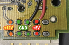
But probably the best course of action would be for me to solder GND and +5V to the main power connector on the motherboard, which would allow the motherboard to be totally removed from the chassis. It wouldn't boot or do anything, but the clock should work normally.

1709157350949.png

I could then use a short spring ground on my scope probe to measure directly across Rp, which is R80 on the LC575.

1709158079798.png

1709157663671.png


Measuring the amplitude with Spicy set to 39MHz, then 43.2MHz, and then yet another higher frequency, would allow me to see if the amplitudes increase as the clock increases.
 
  • Like
Reactions: trag and YMK

JDW

Administrator
Staff member
Founder
Sep 2, 2021
1,577
1,373
113
53
Japan
youtube.com
As you can see from the scope tests below, the higher the CPU clock speed, the lower the voltage across resistor R80, dropping from 3.2Vp-p at the stock clock of 33MHz, down to 2.85Vp-p at 48MHz (via Spicy O'Clock). My scope is a Rigol DHO804 hacked to enable 100MHz bandwidth, with 150MHz rated probes, set to 10X, with the scope channel also being set to the matching 10X. I measured across R80 using a short Ground Spring like this:

1709200844029.png


Bear in mind the LC575 schematic suggests changes to R80 by frequency used, suggesting 121Ω for 20 or 25MHz, 140Ω for 33MHz, and 110Ω for 40MHz. This is interesting because I would normally assume that if you DECREASE the size of R80, the signal amplitude would also DECREASE, since R80 becomes a stronger pull-down resistor as its resistance goes down.

But maybe amplitude is irrelevant here? The peak-to-peak voltage drop across that wide range of 33MHz to 48MHz is not too substantial.

The 68040 User's Manual makes no mention of PCLK amplitude requirements.

The MC88916 datasheet only has this to say on page 6:

The pulse width spec for the Q and 2Q_X outputs is referenced to a VCC/2 threshold. To translate this down to a 1.5V reference with the same pulse width tolerance, the termination scheme pictured in Figure 3 must be used. This termination scheme is required to drive the PCLK input of the 68040 microprocessor with the 88916 outputs.

Please let me know your thoughts. Thanks.

NOTE: The clock signal is indeed a Squarewave, but my scope has only 100MHz bandwidth. If the scope doesn't have at least 5x the bandwidth of the clock signal being measured, the measured signal will display on the scope like a Sinewave. So for the slowest clock of 66MHz below you would really need a 350MHz scope to make it look semi-square. 10x the bandwidth of your measured square wave is better, but still not a perfectly square. To visually see what I am talking about, check out this web page and drag the "c" slider between 1 and 10, which simulates 1x to 10x the bandwidth.

LC575_R80-140ohm_Stock-32.9MHz.png


LC575_R80-140ohm_Spicy-38.8MHz.png


LC575_R80-140ohm_Spicy-44.5MHz.png


LC575_R80-140ohm_Spicy-48.1MHz.png
 
  • Like
Reactions: YMK

JDW

Administrator
Staff member
Founder
Sep 2, 2021
1,577
1,373
113
53
Japan
youtube.com
And one more thing...

Although System 7.1 and 7.5.5 boot fine at 48MHz, System 7.6.1 and OS 8.1 freeze during the boot sequence, even before any icons display. This is consistent with what I've seen in the past at high clock speeds. Reducing the clock speed down to 43.2MHz makes them boot again.

So merely swapping out the DW55 chip for the DW80 doesn't resolve this issue with 7.6.1 and 8.1. I doubt R80 has anything to do with it, since 7.1 and 7.5.5 still boot at high clock speeds.
 

trag

Tinkerer
Oct 25, 2021
280
133
43
Hmmmm. I don't know what's going on internally in the 88916 and the 68040, but looking at the circuit in resistor network terms, changing the value of Rp shouldn't change voltage at the 68040 pin, under some conditions.

The voltage at the Pclock pin should always be Rp X I where I is the current that flows through Rp at any given moment. But I = V/R, suggesting that it completely depends on what V is already present at Pclock. In other words, the voltage would be fixed regardless of Rp, but changing Rp changes how much current gets drained off.

Of course, in an AC circuit, that probably means that draining off more current shaves the peak a bit.

But perhaps the voltage isn't regulated there so much as the current. I vaguely remember things about open source and open drain pins.

Anyway, this suggests that Rp is there to drain away excess current and keep the input to :68040:pclock within current (I) specs. Perhaps at higher frequecies the 88916 outputs more current, or the 68040 sources less? Or one just needs to drain off more current to prevent ringing?

But your waveforms look pretty good. I don't see a bunch of ringing even with the larger Rp still installed.

We may have to warm up the part of our brains with small signal transistor model... But just experimenting is probably more productive.
 
  • Like
Reactions: JDW and YMK

JDW

Administrator
Staff member
Founder
Sep 2, 2021
1,577
1,373
113
53
Japan
youtube.com
I did more testing today. When Spicy O'Clock is set to 43.2MHz, all is well in terms of OS booting and Snooper 2.0 operation. Not only does Snooper 2 launch without freezing, but using my Serial Loopback Plugs, Snooper gives an OK to Printer and Modem testing.

When I move the jumper on Spicy to boost the CPU clock to 48MHz, however, Snooper freezes during launch. I can't even test the serial ports. Even so, I know from past testing that serial ports stop working at just under 44MHz, so this isn't too much of a surprise.

What is interesting though at 48MHz as that using BlueSCSI v2, I cannot boot into 7.6.1 or 8.1. It freezes at the Welcome to Macintosh splash screen, just before any icons appear. However, I can boot into 7.6.1 and 8.1with a spinning platter HDD. So for some reason, the spinning platter drive can keep up with the higher clock speed, but BlueSCSI v2 cannot. And yet, I can boot into 7.5.5 and 7.1 on the BlueSCSI v2 or spinning platter HDD.

We know from the schematic in my earlier post here that R120 pads are shorted via 0Ω resistor, which means Q_DIV_2 is feeding SCSI_Clk. Q would be 48MHz, so that divided by 2 is 24MHz going into SCSI_Clk. And SCSI_Clk is the CK input (clock, pin-86) of the 53C96 SCSI Controller chip. The 53C96 datasheet says the maximum frequency for the CK input is 25MHz, so we can see the issue with BlueSCSI v2 isn't the 53C96 being overclocked. Is something else, although I have no idea what.

I also need to mention this is NOT exclusive to BlueSCSI v2. I tested MacSD and it responded the same. Boots fine into all OSs from 7.1 thru 8.1 at 43.2MHz, but only boots into 7.1 and 7.5.5 at 48MHz. It freezes at the Welcome to Macintosh splash screen on 7.6.1 and 8.1. But again, my spinning platter HDD doesn't freeze.

And these findings are not new. I've know about this since before my XC88916DW55 died.

Would love to hear your thoughts.

1709453616839.png
 

Jockelill

New Tinkerer
Jul 4, 2022
17
13
3
Do you have a SCSI2SD v6? I’ve found that it emulates a mechanical drive better than the BlueScsi. As you know I have issues with rom disk driver and mechanical drives, but it works with BlueScsi (and Zuluscsi, but they use same principle and hardware). I guess the mechanical drives and scsi2sd presents themselves faster to the rom than the BlueScsi is capable of. But would be interesting to see if you see the same difference here. I have unfortunately sold all my scsi2sd, otherwise I could have sent you one.
 

JDW

Administrator
Staff member
Founder
Sep 2, 2021
1,577
1,373
113
53
Japan
youtube.com
Since I mentioned MacSD and BlueSCSIv2 in my previous post (posted 10 days ago) and received no reply until today, I will tag @YMK and @eric so as to glean their thoughts, even if it is speculation. (I'm speaking to Eric outside this thread about it now.)

SUMMARY: With MacSD or BlueSCSIv2, my Mystic boots fine into all OSs from 7.1 thru 8.1 at 43.2MHz, but only boots into 7.1 and 7.5.5 at 48MHz. It freezes at the Welcome to Macintosh splash screen on 7.6.1 and 8.1. But again, my spinning platter HDD doesn't freeze.

This isn't a complaint, mind you. I am just genuinely curious what could be happening on a hardware level that would allow my spinning HDD to work fine with System 7.6.1 and OS 8.1 at higher CPU clock speeds whereas MacSD and BSv2 do not. It's research. :)

Do you have a SCSI2SD v6?
No, unfortunately I do not. But I do have a genuine spinning platter hard drive installed internally in my Mystic, and I can power or kill power to it by yanking out or connecting it's power plug.


@Jockelill
Thank you for having shipped me on of your 8MB Universal ROM SIMMs, by the way. As you and I have been discussing via email, I have been testing that ROM in my Mystic at the lower clock speed of 43.2MHz. As I mentioned in my most recent email to you dated 3/10...

Pressing R & A during the boot sequence will mount the ROM drive and allow reads/writes to it, although I cannot boot from the ROM at all, even when pressing only the R key. And that's true even with my mechanical hard drive disconnected from power and only my BlueSCSIv2 attached externally. I know for a fact my Mystic is booting from my BlueSCSIv2 only and not the ROM SIMM because:
  1. I can see the control panels and extensions and know those are from my BlueSCSI.
  2. I can select all contents of the ROM disk and delete everything, and it will delete. You cannot do that if it is your boot drive.
So even though my mechanical HDD is not powered, my Mystic will only boot from my BlueSCSI and never from the ROM SIMM. The ROM has a System folder with the correct System Enabler, so that is not the issue. And even it it was an Enabler issue, there would be a dialog box presented to me at boot time saying so, but that doesn't happen. So again, I cannot boot my LC575 motherboard from the universal ROM, for some reason.
 
Last edited:

YMK

Active Tinkerer
Nov 8, 2021
358
285
63
SUMMARY: With MacSD or BlueSCSIv2, my Mystic boots fine into all OSs from 7.1 thru 8.1 at 43.2MHz, but only boots into 7.1 and 7.5.5 at 48MHz. It freezes at the Welcome to Macintosh splash screen on 7.6.1 and 8.1. But again, my spinning platter HDD doesn't freeze.

This isn't a complaint, mind you. I am just genuinely curious what could be happening on a hardware level that would allow my spinning HDD to work fine with System 7.6.1 and OS 8.1 at higher CPU clock speeds whereas MacSD and BSv2 do not. It's research. :)

What is the state of the MacSD LEDs when it freezes?

Around that stage of the boot process, MacOS is scanning through SCSI IDs. Might be a long shot, but rearranging the IDs could have an effect.

Is the clock to the SCSI chip affected by your overclocking?
 

JDW

Administrator
Staff member
Founder
Sep 2, 2021
1,577
1,373
113
53
Japan
youtube.com
What is the state of the MacSD LEDs when it freezes?
I cannot answer that question until I test again, which won't be until late tonight after work. Thursdays are my late nights when I don't get home until past 10pm.

Is the clock to the SCSI chip affected by your overclocking?
Yes. As discussed in my earlier post, SCSI_Clk attaches to CK on the 53C96 SCSI controller chip, and SCSI_Clk is feed by Q_DIV_2. So for example, if the CPU is clocked at 48MHz, Q would be 48MHz, and that divided by 2 is 24MHz going into SCSI_Clk, which in turn is 24MHz going into CK of the 53C96 SCSI controller chip.

There's nothing magical about 48.0000MHz either. I simply have my Spicy O'Clock clock driver easily set by jumpers. The middle jumper position let's me drive the 040 CPU at 43.2MHz, and when I move the jumper to the rightmost position on Spicy, the CPU gets clocked at 48MHz. I can of course, tune the clock speed to anything by dialing that into Spicy O'Clock. But for now, I am doing it the fast and easy way, by simply changing Spicy's jumper position.

Again, 43.2MHz is slow enough for everything to work, including serial ports.
 

JDW

Administrator
Staff member
Founder
Sep 2, 2021
1,577
1,373
113
53
Japan
youtube.com
@YMK

Here's a video showing MacSD LEDs during booting into 7.6.1 at 43.2MHz (no lockup) and then at 48MHz (lockup):