Problem with Total Systems '030 accelerator in Plus

JeffC

Tinkerer
Sep 26, 2021
122
79
28
Seattle, WA
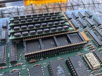
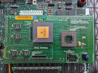
I have a Plus with a Total Systems '030 accelerator that's giving me some problems, I'm hoping someone here might be able to help. I've had the board for years, it sat for a very long time without being used, and a couple years ago when I tried to remove it from the machine, the plastic Killy Clip broke in multiple places and was no longer usable. Recently I had someone solder pin headers onto the 68000 so the accelerator would sit on the CPU without the Killy Clip. It worked at first, though the tall 1mb SIMMs stopped the board from seating on the pin headers completely.

Fast forward a couple of uses (the machine doesn't see much use), I had the accelerator out for some reason, re-installed it and powered on, and the machine wouldn't boot, there was no beep. I re-seated the accelerator and tried again and the machine booted fine. I had already ordered some low-profile SIMMs to allow the accelerator to seat fully, so I set the machine aside until those arrived, assuming everything was fine since the machine had just successfully booted with the accelerator. The low-profile SIMMs showed up, I installed them, installed the accelerator, powered on, and no chime. The screen was mostly black with a few white pixels.

I went through a few different combinations, and the end result is this:
- The machine boots and works fine without the accelerator, with either my 4 original 1mb "tall" SIMMs, or the 4 1mb "low profile" SIMMs
- With the accelerator installed, the machine won't boot, regardless of which set of SIMMs I use.

I have re-seated the accelerator numerous times, I have cleaned the socket and pin headers with DeoxIT, and I have checked continuity between the CPU and the tips of the header pins, just in case there was a broken solder joint somehow. The only connection from the accelerator to the logic board is the CPU socket and the clock signal clip. I have confirmed the clip is on the correct pin, and have also cleaned the clip with DeoxIT.

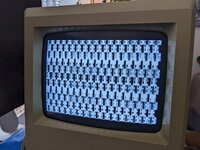
I've attached a couple pics of the screen during the non-boot state. Ever since the accelerator was in its known-working state, I have never handled it without a wrist ground strap, and it has always been stored in an ESD bag when not in use. I'm hoping it hasn't been damaged somehow.

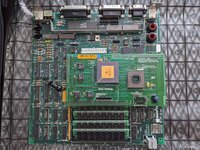
Edit: added a photo showing the location of the clock signal clip. It's difficult to see, but it is clipped onto the end pin of the IC, not the second pin. The clip has an insulated plastic piece that ensures it does not contact the second pin.
 

Attachments

  • PXL_20220516_213148155.jpg
    PXL_20220516_213148155.jpg
    1.4 MB · Views: 82
  • PXL_20220516_212040644.jpg
    PXL_20220516_212040644.jpg
    2 MB · Views: 73
  • PXL_20220702_141625995.jpg
    PXL_20220702_141625995.jpg
    1.8 MB · Views: 71
  • PXL_20220702_145028682.jpg
    PXL_20220702_145028682.jpg
    1 MB · Views: 74
  • PXL_20220516_212035435.jpg
    PXL_20220516_212035435.jpg
    2.3 MB · Views: 72

retr01

Senior Tinkerer
Jun 6, 2022
2,473
1
793
113
Utah, USA
retr01.com
Hi @JeffC! :) 👋 While we are waiting for others to join in, I could try helping you out.
  • It may be the accelerator board itself. Check the traces?
  • And what is the difference between those two garbage screens?
  • Does the black clock clip have continuity?
 
  • Like
Reactions: JeffC

JeffC

Tinkerer
Sep 26, 2021
122
79
28
Seattle, WA
Hi @JeffC! :) 👋 While we are waiting for others to join in, I could try helping you out.
  • It may be the accelerator board itself. Check the traces?
  • And what is the difference between those two garbage screens?
  • Does the black clock clip have continuity?
I haven't taken a really close look at the board with a magnifier or microscope yet, I did take a quick look and didn't see anything damaged, but I can look closer tomorrow.

The two garbage screens are from different attempts to power up. Neither is related to any specific set of conditions. I believe those two were taken a couple minutes apart during different attempts to power up. I have also had a screen that's almost all black with a few white pixels. It seems to vary. A couple times there has been a buzzing sound coming out of the speaker until I turn turn the power back off.

Yes on the clock clip, I checked continuity between the clip, and the solder joint on the board.

Thanks for the help!
 

JeffC

Tinkerer
Sep 26, 2021
122
79
28
Seattle, WA
What about the analog board? Recapped? You mentioned the buzzing sound. That may indicate one of the big caps is giving off that sound.
I hadn't thought about the AB, if it has been recapped it was 25+ years ago. I have a couple other working machines I can swap boards with.
 
  • Like
Reactions: retr01

JeffC

Tinkerer
Sep 26, 2021
122
79
28
Seattle, WA
What about the analog board? Recapped? You mentioned the buzzing sound. That may indicate one of the big caps is giving off that sound.
I tried a known-good analog board with the same results - no change. I also don't know when/if this AB has ever been recapped, but the fact the behavior was the same makes me think it's not the AB. I was able to confirm the buzzing is coming from the speaker and not the caps.
 

Kai Robinson

TinkerDifferent Board President 2023
Staff member
Founder
Sep 2, 2021
1,153
1
1,162
113
42
Worthing, UK
The pattern on the screen is uninitialised RAM - it's displaying whatever is in the RAM at that moment. I had this issue when trying to bring up the SE Reloaded initially - check the 74LS257's at U1F, U2F and U2G.

On the Total Systems Accelerator - the P1 connector pins look a little dull - might be worth reflowing them. U3 looks a little grotty too - check for continuity?
 
  • Like
Reactions: JeffC

JeffC

Tinkerer
Sep 26, 2021
122
79
28
Seattle, WA
The pattern on the screen is uninitialised RAM - it's displaying whatever is in the RAM at that moment. I had this issue when trying to bring up the SE Reloaded initially - check the 74LS257's at U1F, U2F and U2G.

On the Total Systems Accelerator - the P1 connector pins look a little dull - might be worth reflowing them. U3 looks a little grotty too - check for continuity?
Thanks Kai, I'll reflow the P1 connector pins and look at U3 when I get a chance, hopefully this weekend.

I'm not clear on the part about checking U1F, U2F, and U2G. My technical knowledge of these machines is somewhat surface-level. I didn't see parts U1F, U2F, or U2G on the Plus AB, but it's possible I missed them. I also did some searching and didn't come up with anything. Could you provide a bit more detail? I appreciate the help!
 

Kai Robinson

TinkerDifferent Board President 2023
Staff member
Founder
Sep 2, 2021
1,153
1
1,162
113
42
Worthing, UK
The location of U1F etc is easily found by looking at the X and Y axis of the board. Along the bottom, numbers. Along the side, letters. Draw an imaginary line to follow the location. So U2C = the IC located where the number 2 intersects with the letter C :)

Silkscreen nomenclature is:

U = Integrated Circuit
D = Diode
Q = Transistor
R = Resistor
C = Capacitor
L = Inductor
J = Header/Connector
 
  • Like
  • Love
Reactions: retr01 and JeffC

JeffC

Tinkerer
Sep 26, 2021
122
79
28
Seattle, WA
The location of U1F etc is easily found by looking at the X and Y axis of the board. Along the bottom, numbers. Along the side, letters. Draw an imaginary line to follow the location. So U2C = the IC located where the number 2 intersects with the letter C :)

Silkscreen nomenclature is:

U = Integrated Circuit
D = Diode
Q = Transistor
R = Resistor
C = Capacitor
L = Inductor
J = Header/Connector
Great thanks, I spent longer than I'd like to admit looking for a component labeled U1F. 😅
 
  • Haha
Reactions: retr01

retr01

Senior Tinkerer
Jun 6, 2022
2,473
1
793
113
Utah, USA
retr01.com
The location of U1F etc is easily found by looking at the X and Y axis of the board. Along the bottom, numbers. Along the side, letters. Draw an imaginary line to follow the location. So U2C = the IC located where the number 2 intersects with the letter C :)

Silkscreen nomenclature is:

U = Integrated Circuit
D = Diode
Q = Transistor
R = Resistor
C = Capacitor
L = Inductor
J = Header/Connector

That should be a RESOURCE here with some other guides. THANK YOU, @Kai Robinson! :D🙏👏
 

Bolle

Tinkerer
Nov 1, 2021
46
74
18
Have you checked the voltages? The power supply might be bogging down with the extra load of an extra accelerator.
A lot of Plus accelerators back then came with extra power supplies for that same reason.

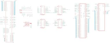
Either way schematics in case you want to check your accelerator against them:
(the schematics only show the PDS connector for the SE version, but the signals are connected straight to the 68000 socket accordingly)

TotalSystems_Mercury.png

GAL dumps: http://wiki.pldarchive.co.uk/index.php?title=Total_Systems_Mercury_(Macintosh_SE_68030_accelerator)
 
  • Like
Reactions: JeffC

JeffC

Tinkerer
Sep 26, 2021
122
79
28
Seattle, WA
Have you checked the voltages? The power supply might be bogging down with the extra load of an extra accelerator.
A lot of Plus accelerators back then came with extra power supplies for that same reason.

Either way schematics in case you want to check your accelerator against them:
(the schematics only show the PDS connector for the SE version, but the signals are connected straight to the 68000 socket accordingly)

GAL dumps: http://wiki.pldarchive.co.uk/index.php?title=Total_Systems_Mercury_(Macintosh_SE_68030_accelerator)

Thanks Bolle, I checked the voltages at the floppy port with the internal floppy disconnected, they are a bit low:

Without accelerator: 4.76, 11.66
With accelerator: 4.72, 11.61

I'll try adjusting the voltage today after work and report back.
 

JeffC

Tinkerer
Sep 26, 2021
122
79
28
Seattle, WA
I adjusted the voltage and unfortunately there was no change. I went up to 12.1v & 5.03v without the accelerator, with the accelerator it dropped down to 11.95v & 4.82v. I also turned it up a bit more until I had 5.0v and 12.2v, no change. The voltage was pretty steady, fluctuating about 0.05v, so between say 4.95v and 5.00v.
 

Crutch

Tinkerer
Jul 10, 2022
293
228
43
Chicago
Those voltages sound fine. I have one of these too, I don’t think this is a PSU issue. Checking for continuity between the accelerator pins and the 68000 and checking the accelerator traces is probably the next stop.
 
  • Like
Reactions: JeffC

JeffC

Tinkerer
Sep 26, 2021
122
79
28
Seattle, WA
Those voltages sound fine. I have one of these too, I don’t think this is a PSU issue. Checking for continuity between the accelerator pins and the 68000 and checking the accelerator traces is probably the next stop.
I'm not using a killy clip any more, I have pin headers soldered to the 68000, and the socket on the accelerator slips over those pins. I checked continuity between the pin headers and the base of the 68000 legs and it seems like all the pin header solder joints are good. I used deoxit to clean the socket that slips over the pin headers, and re-flowed the joints where the socket meets the PCB. The only thing I'm pretty sure of at this point is that I have continuity between the 68000 and the accelerator PCB. 😀

Good suggestion on checking the traces, I did look at them under my microscope a couple days ago and didn't see anything broken, though there is a spot where I think a bit of solder mask flakes off a trace. I should take another look though.