Recreating Macintosh Portable Hybrid Module

Androda

TinkerDifferent Board Secretary 2023
Staff member
Sep 25, 2021
451
490
63
USA, Western
androda.work
In keeping with my latest string of recreations, here's another one.

I am working on recreating the 'hybrid module' from the non-backlit macintosh portable because these tend to die and do stupid things thanks to capacitor fluid damage or the coating cracking off of the high precision laser-trimmed resistors, etc.

This has been a multi-part effort.

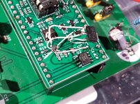
First step was taking the available macintosh portable schematics, and using those to make a 'downstream' board which contains the various power components which are controlled by the hybrid module. So this PCB has mosfets, capacitors, resistors, battery and power supply hookups, etc. This way the recreation modules can be tested without breaking anything on a real portable.

Next, I depopulated a hybrid module from a portable that had been sitting in the desert for who knows how long (thanks @GeekyBit for selling this to me for such a good price). Remove components, measure resistor and capacitor values, trace the schematic, new board created.

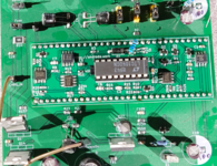
This is my very much prototyping and in-progress setup (#blurrycam):
HybridRecreationPlusDownstream.JPG


What's working so far:
* The primary 5v power rail (called 5V_AlwaysOn, now regulated to 5.25 volts)
* 12v downstream enable (turns mosfets on to allow power to the 12v generator chip)
* -5v downstream enable (turns on the -5 generator circuit which lives on the hybrid module)
* Battery charger
* Battery charge indicator signal
* Battery charge cutoff (HICHG, signal from the power manager chip to disable battery charging)
* Under-voltage cutoff (though it's at 5.4v instead of the 5.6 to 5.8 which is probably more correct)

Things which need more work and testing:
* -5v power rail is all over the place (-6 instead of -5)
* A/D feedback line to power manager (for battery charge level indication - this probably needs testing in a real portable)
* Under-voltage cutoff (as mentioned above, it's a little low but may be ok)

Hardest part about the hybrid module is all of the funky valued resistors. See all the multi-turn adjustable potentiometers on there? And the W-shaped chain of resistors at the bottom of the picture? Yeah. Need to try and find equivalents, or the final product will require micro-trim resistors to be sure the values are all right.
 

Androda

TinkerDifferent Board Secretary 2023
Staff member
Sep 25, 2021
451
490
63
USA, Western
androda.work
Figured out the cause of the -5 volt rail being -6 volts. Counterfeit or bad chips, the whole lot of them. Set up a test circuit on a breadboard, tested about 20 of the chips from my supplier, and none of them were even close.

The original circuit hangs the -5 generator off the battery directly. My changes will probably be to pull from the 5v_alwayson rail because it's only 100mA max. There are cheap and easily available chips to do the inversion, so this is a pretty basic change. Will free up some PCB space too, the new chip is smaller and might remove a component or two.
 

Androda

TinkerDifferent Board Secretary 2023
Staff member
Sep 25, 2021
451
490
63
USA, Western
androda.work
Tweaked a resistor and the under-voltage cutout now acts at 5.59 volts, which is much more survivable for a lead acid battery.

Turns out that a fair few of these custom resistor values are still available as standard SMD resistors, and their values might not necessarily have to be so precise.

Most of what remains now is to rework with SMD parts and use a different -5 generator chip, which I've already selected. That will be a testable "beta" design that doesn't have wires and stuff sticking everywhere.
 

Androda

TinkerDifferent Board Secretary 2023
Staff member
Sep 25, 2021
451
490
63
USA, Western
androda.work
I did see at least some of what silicon insider is doing on 68kmla. This is an approach I had considered before going down the route of just recreating the existing hybrid.

It seems like a really simple idea to stick a 5v regulator in there, but that doesn't take into account the variety of other things which the hybrid does. Some of these functions are at least semi-simple like switching on and off the -5v and 12v generators.

There are also more difficult things to manage, such as the interaction with U7M on the motherboard which regulates 5v for hard disk (and enables 12v hard disk too). There's also battery charging that interacts with Q1 on the motherboard to control battery charge rates or cut off charging entirely (trickle charge, basically) when HICHG is flagged, and the A/D feedback voltage to the power manager that signals battery charge levels.

So yeah. There's nothing stopping you from pulling out mosfets and other components, along with running thicker gauge wiring around to handle currents and stuff. Changing out the control system from hybrid to something else is absolutely doable. But I think that level of modification will end up being more complex to manage than recreating the hybrid itself.

Changing out just the hybrid will overall be easier than changing out the hybrid plus all the downstream components that get in the way of a control override system.
 

mg.man

Tinkerer
Oct 20, 2021
122
59
28
Ardley, UK
I did see at least some of what silicon insider is doing ... It seems like a really simple idea to stick a 5v regulator in there
Cool, just mentioning. I do think he's considering a replacment for the Hybrid - but with more modern design?

In any case, I do agree it would be more simpathetic to the design to not go hacking about and to replace the Hybrid, so will be watching both efforts.

FWIW, SI's work did allow me to confirm there's definitely hope for one of my Portables...

20220318_182208.jpg


That's it powered with a single 5V feed to Q16. :)
 
  • Wow
Reactions: RetroTheory

Androda

TinkerDifferent Board Secretary 2023
Staff member
Sep 25, 2021
451
490
63
USA, Western
androda.work
Some progress has been made on the hybrid recreation. I assembled my new SMD style one and gave it a shot.

Under-voltage lockout is now up to 6 volts, which is just about right for a 6v lead acid battery. Discharge much lower than this and you risk battery damage.

The -5v generator isn't quite working right, something about the mosfet I used for switching it is wrong. Only getting -3 volts instead of -5. Probably just needs a mosfet with lower 'on' resistance.

I also have the A/D line (battery voltage level reporting to the power manager chip) a little more figured out. By tweaking some resistor values it's reporting about 4.5 volts when plugged in and the battery is charging at around 7.5 volts. The documentation I can find says that A/D should be up to 5 volts, so 4.5 volts is right about there.

The A/D line is much lower when on battery, and I'm not sure what it should be.

And there are two other resistors that still need to be sorted out. There's an NTC resistor in parallel with another resistor. My combination wasn't resulting in the same parallel resistance as a test hybrid module, so that was hard-set with a full size standard resistor.

Really all that's left to figure out are the A/D line and -5v generator. Getting close to something workable.
 

Attachments

  • SMD_Hybrid.png
    SMD_Hybrid.png
    822.5 KB · Views: 99

Androda

TinkerDifferent Board Secretary 2023
Staff member
Sep 25, 2021
451
490
63
USA, Western
androda.work
30 second update:

-5 will be fixed with the next PCB revision (see attached bodge wire nightmare test of the new -5 system).

All that remains are the mysteries of the A/D line. I've considered throwing away the complicated op-amp system for something totally basic like a resistor divider that reports 66% of the current battery voltage. It would be inaccurate compared to the original, but maybe good enough.
 

Attachments

  • -5_Mosfet_Test.JPG
    -5_Mosfet_Test.JPG
    236.8 KB · Views: 81
  • Like
Reactions: Nitram78

Androda

TinkerDifferent Board Secretary 2023
Staff member
Sep 25, 2021
451
490
63
USA, Western
androda.work
The results on the latest hybrid PCB are in:
* I had a resistor in the wrong place (bodge wires plus extra resistor required, already fixed for next PCB revision)
* -5 volt rail works on the tester board after ^

Next up, I desoldered the hybrid module from a 5120 I've had for awhile. This one generally speaking doesn't want to start up, but trying over and over again it would eventually relent and turn on. This hybrid recreation was put in its place, and...

Hybrid-FirstBoot.JPG


It works!

This test was performed with battery replaced by a 6.7 volt power supply. I have since tested with a real lead acid battery, and the results are mixed (as expected). With battery (and battery cover) installed *and the power adapter plugged in*, the Portable happily boots and behaves normally. On battery alone, the A/D line drops too low and very rapidly you get the 'this computer is shutting down in 10 seconds to preserve memory contents' message.

So this is currently a working solution for those that want to run their portable on power adapter (with battery present). I will be doing more looking at the A/D line situation to try and come up with a solution for running on battery power.

Overall I'd say this is a success.
 

Androda

TinkerDifferent Board Secretary 2023
Staff member
Sep 25, 2021
451
490
63
USA, Western
androda.work
It appears that the time has fully arrived: The A/D line is fixed, or close enough to the original that it behaves the same way.

One resistor value wasn't quite right (basically the same thing I've said over and over again thus far).

I can now run my Portable on battery power without it instantly saying "you have 10 seconds until the system goes to sleep". The battery meter shows empty near 6 volts and full near 6.7 volts (on the battery terminals), which is just about right.

A hopefully-final-revision PCB will be ordered soon, and then production can begin.

edit: Forgot to mention that I sent one of these to @techknight , hopefully he doesn't find anything seriously wrong with it.
 
Last edited:

Androda

TinkerDifferent Board Secretary 2023
Staff member
Sep 25, 2021
451
490
63
USA, Western
androda.work
Digging around a bit, I found an dual opamp which hopefully can replace the original (and hard to find) opamps with one newer and cheaper chip. Going to pursue that as a possible update to the design before officially producing these. Less reliance on vintage parts is better. Haven't found anything to replace the big chip yet (LTC1040).
 

Androda

TinkerDifferent Board Secretary 2023
Staff member
Sep 25, 2021
451
490
63
USA, Western
androda.work
That other opamp possibility didn't turn out to work, because it was too high a slew rate. Going to try another one, because supply of the original opamp is drying up and I don't have many of them.
 
  • Like
Reactions: TimoB

TimoB

New Tinkerer
Jul 11, 2022
5
0
1
Hi, this is super exciting! I resurrected a dead Portable (non backlit) a couple of months ago by cleaning, recapping and fitting a bluescsi. It runs off the wall socket okay but on battery will last only a short while until the "10 seconds remaining" message. Also the charging circuit seems to be out of order, I think neither the high or low cutoff do work.

I'll be more than happy to test the hybrid replacement, will drop you a mail!
 

Androda

TinkerDifferent Board Secretary 2023
Staff member
Sep 25, 2021
451
490
63
USA, Western
androda.work
@techknight has tested the one I sent over, and it's basically working. Revived a Portable that had been sitting around for something like 7 years.

The caveat here is that the battery meter on his portable doesn't go all the way to "full "when it should. This is interesting, because testing the same resistor values on my portable does fill the battery meter completely at full charge voltage. We might have to add a micro-trimmer potentiometer to the design to allow for the specific resistor (which I've labeled R11) to be adjusted.

Another issue is that my source of the original opamps (OP-20H) has just about dried up. I have two more types of opamps on the way to be tested for usability, which will probably arrive today.


On a semi-related note, how many people are still trying to use Portables on battery power, in a 'mobile' fashion? Would you be interested in a solution which requires the portable to be plugged in, but doesn't die every 6 months to a year due to the lead acid battery going bad?
 

ScutBoy

Administrator
Staff member
Founder
Sep 2, 2021
329
306
63
Northfield, MN USA
On a semi-related note, how many people are still trying to use Portables on battery power, in a 'mobile' fashion? Would you be interested in a solution which requires the portable to be plugged in, but doesn't die every 6 months to a year due to the lead acid battery going bad?

Yes! :)

I've got a Backlit, and I am a bit tired of "maintaining" and replacing batteries...
 
  • Like
Reactions: Nitram78

Androda

TinkerDifferent Board Secretary 2023
Staff member
Sep 25, 2021
451
490
63
USA, Western
androda.work
Here's a fun tale about the differences between older parts and more modern ones.

I have found a replacement opamp that works in place of the original OP20H. But this new opamp was causing odd behavior, where the 5v rail would *sometimes* (not all the time) spike up to full battery voltage for about a second before falling to the expected 5.2 volts and never spiking again. After poking around at the circuit and re-reading the datasheets I made a fun discovery.

First, a little background. The 1040 chip is responsible for turning on the 5v regulator opamp by supplying its VCC voltage when the opamp should be enabled. Sounds simple enough, but this actually gets quite tricky with modern components.

The original OP20H does not work when its VCC supply is at less than about 4 volts. Inputs and outputs are disabled below that voltage, and the hybrid has a resistor to pull the 5v regulator mosfet to 0 volts in this case. This is the desired behavior, if the opamp is turned off then shut down primary 5v supply.

The new opamp works down to about *2 volts on VCC*. So if there's a battery wire glitch or the battery bounces on the spring terminals, the 1040 loses power for a moment. It immediately disables the voltage output that powers the 5v regulator opamp, *but the internal timer keeps running* (it's a timed sample system). If power is restored before the internal timer stops working (all the way down at 2 volts or so), it won't sample again until the timer elapses. During the time that the 1040 has not sampled again, there's still 2 volts on the 5v regulator opamp's inputs - more than enough to start working, but *not enough to control the 5v regulator mosfet*. Thus the 5v output pops up to the full battery voltage for a harrowing moment until the 1040 samples again and ups VCC on the opamp to what it should be. Once VCC is up enough, the opamp is immediately able to regulate 5v again and all is well.

More or less, the OP20H has a free, built in switch that only works above 4 volts. 4 volts is plenty to control the 5v regulator mosfet, so there are no issues ever with the original part. Given that the new part works down to practically nothing, a simple fix was needed.

I have bodged on a mosfet which listens to the output of the 1040 and does not enable the 5v regulator signal output until the 1040 sends full VCC voltage to the opamps. This mosfet switch solution seems to be working perfectly. No matter how I abuse and glitch the voltage input, the new opamp always causes the correct 5.2 volts to be output on the main 5v rail.

Summary:
When replacing older components with new ones: watch very carefully for their operation voltage ranges, things might be running when you would expect them not to be - simply because new process technology enables very low voltage operation.

What you should expect:
I am reworking the design to only use the new opamps because really it doesn't make a lot of sense to me to have several designs floating around using both vintage and modern parts. *This is going to cause a delay in testing until I have the new designs in hand*, but will be a better long term solution that relies on fewer new-old-stock vintage parts. All that remains to be eliminated is the 1040 chip itself, but that chip has plentiful stock from my supplier and is even still available new.
 

Androda

TinkerDifferent Board Secretary 2023
Staff member
Sep 25, 2021
451
490
63
USA, Western
androda.work
After prototyping around a little more with opamps, I have sent in a new PCB design for manufacture. As mentioned in my previous post, this will be using all-new opamps instead of new-old-stock for better parts availability.

The machine pin headers that are necessary for installation (mounting holes for the hybrid are very small) are delicate and easy to break. This leaves me with a bit of a problem to solve, because I want to test these before shipping out. This means either some sort of spring pogo pin and 3d printed clamp solution, or perhaps a 3d printed 'hybrid puller' that exerts equal force across the bottom of the module to ensure pins don't break on removal from the portable I use for testing.