TashRecorder: a Farallon MacRecorder compatible clone
- Thread starter demik
- Start date
-
- Tags
- macrecorder
You are using an out of date browser. It may not display this or other websites correctly.
You should upgrade or use an alternative browser.
You should upgrade or use an alternative browser.
Are there instructions available for using the device in MIDI Interface Mode? For example, how to wire it to a standard 5-pin or other MIDI connector?
I asked @Tashtari directly on discord and this was the reply:
The firmware can support it, but demik's board doesn't support that at the moment.
Personaly, I'm all for an exclusive MIDI interface as a cheap standalone - more people would be after that and it wouldn't force the higher cost of the MacRecorder upon it.
as @Tashtari said, the device as you know it (that translucent bluebox that I posted that @Mu0n built in his nice video) is unfortunately audio only (Internal Mic or external line in). Long answer below
Citing MIDI in that small box was hard and the BOM was going a little crazy (need other switches, opto couplers and probably Mini DIN to DIN adapters such as this one
As I have no MIDI device myself, I was hoping someone else could respin the PCB (as you may imagine I'm not a fan of shipping stuff that I cannot test). @Mu0n idea is good as well, doing a separate box using the same microcontroller/firmware
However if you would like to experiment we added a header to help people prototype such things. Here are the undocumented header (J3) layout:
- +2.5V (virtual +5V)
- audio (MIDI IN goes there, remove op amp)
- MODE (Connect to pin below to switch to MIDI mode)
- -2.5V (virtual GND)
The ±2.5V power thing of TashRecorder is floating centred to the Mac Ground so the PIC is able to transmit on spec RS422 signals and is also more convenient to work with audio signals
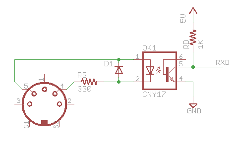
The idea is to build (externally) something like this with an 6N138 optocoupler (schematic from an unrelated project)
Maybe @Tashtari got it further but that's all I had on my notes
Hope it helps
Citing MIDI in that small box was hard and the BOM was going a little crazy (need other switches, opto couplers and probably Mini DIN to DIN adapters such as this one
As I have no MIDI device myself, I was hoping someone else could respin the PCB (as you may imagine I'm not a fan of shipping stuff that I cannot test). @Mu0n idea is good as well, doing a separate box using the same microcontroller/firmware
However if you would like to experiment we added a header to help people prototype such things. Here are the undocumented header (J3) layout:
- +2.5V (virtual +5V)
- audio (MIDI IN goes there, remove op amp)
- MODE (Connect to pin below to switch to MIDI mode)
- -2.5V (virtual GND)
The ±2.5V power thing of TashRecorder is floating centred to the Mac Ground so the PIC is able to transmit on spec RS422 signals and is also more convenient to work with audio signals
The idea is to build (externally) something like this with an 6N138 optocoupler (schematic from an unrelated project)
Maybe @Tashtari got it further but that's all I had on my notes
Hope it helps
I've done that MIDI in subcircuit on breadboard and perfboard a number of times and it worked well with my stock of H11 optocoupler chips from Ali express.
A midi interface typically needs to have a 1MHz oscillation signal divided by exactly 32 to get to the midi spec's 31,250 bps. Is that what the firmware can achieve already?
A midi interface typically needs to have a 1MHz oscillation signal divided by exactly 32 to get to the midi spec's 31,250 bps. Is that what the firmware can achieve already?
Yeah - in MIDI mode (mode select pin pulled low), the firmware generates a 1 MHz clock from the clock output pin and relays the MIDI/audio input pin to the RxD± pins, inverted.A midi interface typically needs to have a 1MHz oscillation signal divided by exactly 32 to get to the midi spec's 31,250 bps. Is that what the firmware can achieve already?
Thanks to @Mu0n's group buy of PCBs, I was able to build one during my livestream last night. The only issues I had were component fitment issues: the LED had leads that were too short, and the resistors that get mounted parallel to the PCB were too large to fit flat. The resistor issue isn't a big deal, but I had to find another LED from an assortment that I had.
And it worked - happy dance! I tested it on my Mac LC of rEgrets running System 7.1.
And it worked - happy dance! I tested it on my Mac LC of rEgrets running System 7.1.
Great to see another build!Thanks to @Mu0n's group buy of PCBs, I was able to build one during my livestream last night.
To follow up on the questions about MIDI raised in the chat and the video:
The PIC firmware was created with the idea of making it possible to make a two-in-one device that emulated both the MacRecorder and the Apple MIDI Interface. This is still doable but would require a different board/case design - the decision was made to make this board MacRecorder only due to space constraints. The board and case are pretty crowded as it is, and fitting the requisite components for MIDI (not the least of which is a big full-size DIN connector) was not feasible without significant changes, such as going to surface-mount components and/or using a larger case.
The four-pin header you noticed was added with the idea of maybe adding MIDI support later, possibly with a daughterboard or something, but a provision would still have to be made for switching the input and it's just not realistic to fit it all in there.
Happy TashRecording!
Thanks to @Mu0n's group buy of PCBs, I was able to build one during my livestream last night. The only issues I had were component fitment issues: the LED had leads that were too short, and the resistors that get mounted parallel to the PCB were too large to fit flat. The resistor issue isn't a big deal, but I had to find another LED from an assortment that I had.
And it worked - happy dance! I tested it on my Mac LC of rEgrets running System 7.1.
Glad to hear about another success!
After looking at this LED issue, the error is mostly on my side, sorry about that. What happened: the SSL-LX5093SRC39240 is similar to the SSL-LX5093SRC/E except cheaper and with short leads. Except the LX5093SRC39240 pictures show a LED with long leads. Always check the data sheet folks
")
The correct cart link is now d27bf9f90a, Github PR done
If other people have the wrong LED, you can workaround this by using leftover cuts from another component (example: capacitor leads)