WarpSE: 25 MHz 68HC000-based accelerator for Mac SE

Zane Kaminski

Administrator
Staff member
Founder
Sep 5, 2021
266
462
63
Columbus, Ohio, USA
Recall how Woziank used the fewest possible chips and paths to build the first Apple compared to other engineers of the day who used too many chips and paths?
Yeah, that's usually our aim. Hence why the previous hardware revision of the NuBus WiFi card was rejected. 40 chips! They're all like $0.25 each but we can just use an FPGA instead.

I am wondering about the PDS pass-through and the number of cards. Since it is better to forgo the pass-through PDS stuff on the new accelerator cards, what about a dedicated PDS expander card that passes through and does not slow down or meddle with anything? Alternatively, would an all-in-one PDS card make sense to modernize a Mac SE or SE/30 down the road? Give the SE or SE/30 acceleration, 24-bt color video out (VGA and HDMI), and networking (802.11n, ac Wifi, or RJ45 Ethernet) to save money versus multiple PDS cards and PDS pass-through cards?
We realized a long time ago that we have to do this stuff with the "minimum viable product" approach. We can't go right for the all-in-one gizmo. It would be too complicated, take too long to develop, cost too much money in every way (per unit, prototyping costs, setup costs, initial batch), etc. Instead we have to analyze the problem and find one thing that's doable and which, when finished, will deliver some functionality that people will enjoy and pay for so that we can make a little money and play another round of the hardware company game. If we commit to making some kind of all-in-one gizmo, the price will be high, the market small, and it's a lot of work and investment before we can sell any and put money back in the GW bank account. And we might have to cancel it as we did the WarpLC!

And I have to say, we make bad decisions and lose money a lot lol, for example by entering the 30-pin RAM SIMM market. Terrible decision! I am not sure we made any money selling RAM SIMMs, but yet we spent a lot of time doing RAM SIMM stuff. If we did make money, it was only because of our luck in purchasing several gigabytes of military-temperature-grade legacy DRAM chips back in 2019 at an exceptionally good price. The margins in RAM SIMMs are low, you have to beat the price of everyone else, the RAMs get lost in the mail and you have to resend them, the distributors of the legacy RAM chips keep raising the prices, the customers want help with why it won't work in their obscure 386 clone, etc. We thought all we had to do was master the quality of the electronics. Totally wrong! So it's good we had other products which were successful in putting money back into the R&D fund while we were busy wasting time and money on our bad decision getting into the 30-pin SIMM market. Imagine if we were screwing up in RAM SIMMs and simultaneously trying to pay for the initial batch of some fancy all-in-one gizmo. Well, GW never gets in debt, so "insolvency" is the wrong word, it'd be more like "out of gas."

So therefore we have to sort of find one step we can take, do that, and if that turns out good, try and find another development to pursue and maybe combine them. That's how to get to the all-in-one gizmo. But there is a lot of variance in the ultimate impact of one development so having a good strategy in choosing what to work on is important. Lemme illustrate.

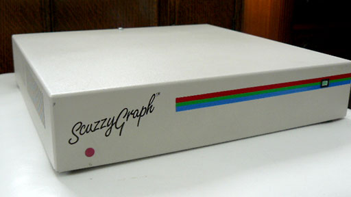
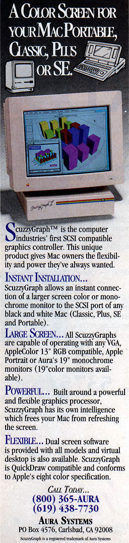
The WarpSE is great and we fully intend on producing and supporting it for a long time (hence our desire to switch to FPGA-based CPU), but the WarpSE is sort of a dead-end. Other than modernizing the RAM and CPU, there are few unambiguously good changes to make. We could add networking! But I think it's better to do it with one of those new SCSI-to-WiFi gizmos. That way it's separate from the accelerator so people who don't know about accelerators but do know about networking can work on improving it. Okay, well we could add a second video output to the WarpSE! But the Mac SE doesn't have Color QuickDraw so it would only be 1-bit. And actually the OS itself doesn't support multiple monitors on the SE like on the Mac II and subsequent machines. To support drawing to multiple monitors, video card drivers for the SE have to patch QuickDraw and there are more compatibility issues compared to on a Mac that's supposed to have multiple displays. So the WarpSE is good but it's a bit of a dead-end. There's nothing really great to add to it and it, being an accelerator, is not something you really think of "adding" to another gizmo.

Now consider the NuBus WiFi card. It's much less of a dead-end. We can make the WiFi card and it would be popular. But then we could take the existing drivers, FPGA code, etc., remove the NuBus stuff, and attach it directly to an accelerator. That would be easy. And since the NuBus card is a separate (and less expensive) thing than the accelerator but shares all the drivers and stuff, there isn't the barrier to contributing that I was referring to earlier. If you are intimidated by improving the WiFi card in the context of the accelerator, you can improve it in the context of the NuBus card and anything you do will directly transfer over.

Putting it all together, networking and video output are much more coveted on an SE/30 than on an SE. Therefore we could design the WarpSE accelerator without having the other pieces (networking and video) but we couldn’t do the SE/30 accelerator without those. So we started the WiFi card and WarpLC projects. The WarpLC was supposed to have the WiFi card in it, but the WiFi module only costs a few bucks so we could just advertise the card as an accelerator. Once the WiFi card was finished, we could do a software update on the WarpLC and add WiFi. But even if we never finished the WiFi card, no big deal, the WarpLC would be okay without WiFi. Then with both the WiFi card and WarpLC in hand, the single big goal for the WarpSE/30 would have been the video subsystem since we could reuse most of the WarpLC and the WiFi stuff.

So we are eager for the chip shortage to be over so that we can figure out how to resume the plan I just described, incrementally building up into a great all-in-one gizmo which we can port to the various 68030-based Macs.

Edit:
Oh, regarding the pass-through card, yeah, if we did come out with an accelerator without video or networking, there would be no reason you couldn't make a splitter PDS card to hook up both the accelerator and your other card.
 
Last edited:

retr01

Senior Tinkerer
Jun 6, 2022
2,469
1
782
113
Utah, USA
retr01.com
But the Mac SE doesn't have Color QuickDraw so it would only be 1-bit. And actually the OS itself doesn't support multiple monitors on the SE like on the Mac II and subsequent machines. To support drawing to multiple monitors, video card drivers for the SE have to patch QuickDraw and there are more compatibility issues compared to on a Mac that's supposed to have multiple displays. So the WarpSE is good but it's a bit of a dead-end. There's nothing really great to add to it and it, being an accelerator, is not something you really think of "adding" to another gizmo.

Yes, up to the Color Classic, compact Macs have been 1-bit because of the CRT and other factors. That is true that to support drawing to external monitors, the usage of QuickDraw is necessary.

Apple's QuickDraw has supported 8-bit color, not to be confused with the later Color QuickDraw that supported more extensive color palettes. In 1987, an external SCSI color video-out was available for the Macintosh Plus and SE. ScuzzyGraph was an external SCSI case that sustained color video output to a color monitor via RGB with a limited color palette at 3 or 4 bit. 😍

scuzzygraph-front.jpg
scuzzygraph-rear.jpg
scuzzygraph-ad-hr.jpg

Source: https://lowendmac.com/2013/scuzzygraph-and-scuzzygraph-ii/

The SE has a SCSI connector on the logic board (LB). It may be possible to take advantage of that for a small color video board, about the size of the Raspberry Pi Zero that is situated vertically, with SCSI pass-through for the internal SCSI HDD or SCSI SD adapter. For the Plus, externally would be the way to go unless the SCSI connector is installed on the LB, but that may not be easy.

Besides the budgetary issues back in the day for the production of computer hardware with strict design guidelines, I think Apple stood by their decision for compact Macs until the Color Classic to remain 1-bit video as the true-type font text was much crisper and precise on the screen compared to CRT color monitors of the day that tended to be a tad blurry.

Putting it all together, networking and video output are much more coveted on an SE/30 than on an SE. Therefore we could design the WarpSE accelerator without having the other pieces (networking and video) but we couldn’t do the SE/30 accelerator without those. So we started the WiFi card and WarpLC projects. The WarpLC was supposed to have the WiFi card in it, but the WiFi module only costs a few bucks so we could just advertise the card as an accelerator. Once the WiFi card was finished, we could do a software update on the WarpLC and add WiFi. But even if we never finished the WiFi card, no big deal, the WarpLC would be okay without WiFi. Then with both the WiFi card and WarpLC in hand, the single big goal for the WarpSE/30 would have been the video subsystem since we could reuse most of the WarpLC and the WiFi stuff.
Good plan. :) Avoid reinventing the wheel. Modernize the wheel, though, to improve efficiency. (y)

So we are eager for the chip shortage to be over so that we can figure out how to resume the plan I just described, incrementally building up into a great all-in-one gizmo which we can port to the various 68030-based Macs.
I think the IC (integrated circuitry or "chips") shortage will linger long. Even if the ICs become more available, legacy ICs will become much more expensive or unobtainium. It would be good to look into using modern ICs such as FPGA to emulate legacy ICs designed to operate, which GW is doing. 👏

Edit:
Oh, regarding the pass-through card, yeah, if we did come out with an accelerator without video or networking, there would be no reason you couldn't make a splitter PDS card to hook up both the accelerator and your other card.
For sure! 😎

There are software and operating system limitations, even with modern help for the compact Macs and other legacy computers (Apple II, Amiga, Atari, Macs, etc.). I do not see that we have enough software engineers (programmers) to help with the efforts to create games, OS updates, and other apps for the 68k Macs? :unsure:
 

Zane Kaminski

Administrator
Staff member
Founder
Sep 5, 2021
266
462
63
Columbus, Ohio, USA
@retr01 Thing about the ScuzzyGraph is, it's quite complicated from a software perspective. The ScuzzyGraph driver intercepts commands sent to Quickdraw, checks if they are destined for the external screen, and if so, packetizes the command and sends it over SCSI to the ScuzzyGraph external unit. The external unit has a Texas Instruments TMS34010 graphics processor and its own implementation of Quickdraw. It executes the commands as received from the Mac and paints the result onto the screen. So it's complicated to because the external unit has to have its own perfect implementation of Quickdraw. The TMS34010 chip is very hard to obtain, much harder than a 68030 or whatever. So a direct reproduction is not a good idea. Maybe someone can run the ScuzzyGraph ROM on a TMS34010 emulator on an ARM microcontroller connected to the requisite SCSI and video interfaces. That'd be cool! Also original Quickdraw is only capable of 8 colors (i.e. 3-bit) and only in certain contexts. The 8-color mode is mainly for printed documents. So I don't think color icons would appear in the Finder, for example. I think the color is limited to contexts where the routine for color printing is shared with the routine for displaying the document on screen.

Regarding how the ScuzzyGraph works, has it occurred to anyone that you could do this same thing between two Macs connected with Ethernet? 10 Mbit Ethernet is basically the same speed as SCSI on the Mac Plus so you could conceivably pipe the Quickdraw commands over Ethernet instead. The Mac on the receiving side would run a little app that shows the second screen of the sending Mac. Funny thought.
 
  • Haha
Reactions: retr01

retr01

Senior Tinkerer
Jun 6, 2022
2,469
1
782
113
Utah, USA
retr01.com
Regarding how the ScuzzyGraph works, has it occurred to anyone that you could do this same thing between two Macs connected with Ethernet? 10 Mbit Ethernet is basically the same speed as SCSI on the Mac Plus so you could conceivably pipe the Quickdraw commands over Ethernet instead. The Mac on the receiving side would run a little app that shows the second screen of the sending Mac. Funny thought.
Oh yeah! Good one! A series of compact Macs playing the telephone game. I wonder if those Macs would exhibit a slight deviation, perhaps after removing the error correction protocol?

@Zane Kaminski, thank you for expanding how ScuzzyGraph managed the color output. It is fascinating seemingly impossible was achieved back in the day with limited technological capabilities. Nowadays, billions of colors are possible on computers.
 

retr01

Senior Tinkerer
Jun 6, 2022
2,469
1
782
113
Utah, USA
retr01.com
Now back to the topic.

I was thinking about the developments Garrett's Workshop has been doing to help make the compact 68k Macs more useful with acceleration and other things. I learned that the Mac Plus (and maybe the SE) is limited to 4 MB of RAM because it only addresses 22 of 24 lines on the logic board (LB).

I wondered if there is a way to add two more lines, so perhaps it could address higher RAM capacities? I looked at the schematics for the LB and on the LB itself. I understand that 22 lines only can access up to 4 MB, whereas 24 lines can access up to 16 MB. I realize some accelerators back in the day for the Plus enabled access up to 16 MB because of 24 lines to address up to 16 MB.

So, for the WarpSE, will it have 24-line addressing? Or more to address more memory? I missed something.
 

Zane Kaminski

Administrator
Staff member
Founder
Sep 5, 2021
266
462
63
Columbus, Ohio, USA
So, for the WarpSE, will it have 24-line addressing? Or more to address more memory? I missed something.
Yeah, adding more ram isn’t too straightforward. From a hardware perspective it’s easy as you mentioned, just add more RAM and utilize the corresponding address wires. It’s a software problem. The ROM software is programmed with an assumption that devices such as ROM, floppy SCSI, etc. are placed in the Mac’s memory map at specific locations beyond the 4 MB mark. So if you put more RAM there, it would be getting in the way of the I/O devices, and the OS wouldn’t know how to use the extra RAM either. There is some software which can assist with this and let an accelerated Plus/SE use more RAM but it requires a 68030 and its built-in MMU rather than the 68HC000 on the WarpSE.

I do have a different, more software-oriented approach to to adding more RAM without a 68030 and its MMU. It requires modifying the memory manager in the Mac OS. We could even prototype it using the WarpSE hardware, although since the WarpSE only has 4 MB or RAM, we would have to also use the slow motherboard RAM and the card would not work very well as an accelerator. But we can try it and if it works well, it would be easy to enhance the WarpSE with more RAM in the next version with the FPGA core.
 
  • Like
Reactions: retr01

retr01

Senior Tinkerer
Jun 6, 2022
2,469
1
782
113
Utah, USA
retr01.com
Yeah, adding more ram isn’t too straightforward. From a hardware perspective it’s easy as you mentioned, just add more RAM and utilize the corresponding address wires. I
Right.

t’s a software problem. The ROM software is programmed with an assumption that devices such as ROM, floppy SCSI, etc. are placed in the Mac’s memory map at specific locations beyond the 4 MB mark. So if you put more RAM there, it would be getting in the way of the I/O devices, and the OS wouldn’t know how to use the extra RAM either. There is some software which can assist with this and let an accelerated Plus/SE use more RAM but it requires a 68030 and its built-in MMU rather than the 68HC000 on the WarpSE.
Aha! So, how is going beyond the 4 MB achieved if there is only 4 MB physically installed? I am aware there is high and low memory and that various instruction sets are placed in multiple locations in the memory. ROM has memory itself as well. For example, 512k ROM SIMM in the SE/30? Yet, isn't that 512k already filled up with the instruction sets?

I do have a different, more software-oriented approach to to adding more RAM without a 68030 and its MMU. It requires modifying the memory manager in the Mac OS.
ResEdit the Finder, right? Loading an INIT at startup that will populate the instruction sets to modify the memory manager? Are you planning to do Assembly Language or C?

We could even prototype it using the WarpSE hardware, although since the WarpSE only has 4 MB or RAM, we would have to also use the slow motherboard RAM and the card would not work very well as an accelerator. But we can try it and if it works well, it would be easy to enhance the WarpSE with more RAM in the next version with the FPGA core.
Why not start with 4MB on the card? AppleSqueezer, the new accelerator for the Apple IIGS, provides 14 MB of RAM via modifying the GS System 6 Finder so the IIGS can use 14 MB of RAM in the accelerator. No memory card is needed on the IIGS LB. The accelerator, essentially an FPGA, actually has more than 14 MB of RAM. So, just put a lot of memory on the card that can be unlocked to 8 MB and go up at the appropriate stage of development once everything goes well with 4 MB.
 

Patrick

Tinkerer
Oct 26, 2021
434
1
223
43
has it occurred to anyone that you could do this same thing between two Macs connected with Ethernet? 10 Mbit Ethernet is basically the same speed as SCSI on the Mac Plus so you could conceivably pipe the Quickdraw commands over Ethernet instead.
Somebody did something like this for the Apple ][ . .. well the idea of sending video commands over a network i mean.

they took a webcam, converted each frame to Apple ][ graphic commands. (i forget which mode) and sent those over to an apple //e i think...

I think it was charles mangin who did it. but i can't find the kfest entry where he shows it off.

the result was that you had video from a camera being displayed on an Apple ][ of some kind that one would think shouldn't be possible to do.
 
  • Wow
Reactions: retr01

Zane Kaminski

Administrator
Staff member
Founder
Sep 5, 2021
266
462
63
Columbus, Ohio, USA
I bought an SE motherboard and hooked it up to the power/video converter thing:
1655634752675.jpeg


No WarpSE connected yet. I just wanna get the display thingy working. Unfortunately none of my displays like the Mac's sync timing. Here was the best I got on my HP L2335:
1655634670105.jpeg

The color is inverted but that's not the real issue. The problem is the HSYNC frequency is too low and the pulse width is too wide. Maybe I can find another screen that works with it, otherwise I have to get one of those RGB2HDMI-type gizmos.
 

retr01

Senior Tinkerer
Jun 6, 2022
2,469
1
782
113
Utah, USA
retr01.com
The color is inverted but that's not the real issue. The problem is the HSYNC frequency is too low and the pulse width is too wide. Maybe I can find another screen that works with it, otherwise I have to get one of those RGB2HDMI-type gizmos.

Hi @Zane Kaminski! :)👋

Yup, you will need the R Pi Zero and RGB2HDMI. (y);)

Additionally, you may need to build a low-tech wiring adapter for B/W output. I have a Power R 2703 video adapter for SE and SE/30 that taps video from the logic board (LB) between the LB's connector and the harness to the analog board (AB), to output B/W 1-bit video via TTL. 🤓☝️

Here is the general connection pathway:

1655651499316.png

Note: Technically, an analog board is not needed
for the compact Macs prior to the Mac Classic and
Classic II for video out to a modern display.

Unfortunately, those are very rare to find nowadays. 😔

Fear not! 😃 There is hope! (Star Wars theme music plays) In a galaxy far away, @Stephen created a GitHub on cloning the Power R 2702. 🤩 I was planning on forking from his GitHub for the SE and SE/30 version. Maybe you can help me with that? Between Power R model 2702 for the 128k, 512, and Plus and Power R model 2703 for the SE and SE/30, the specs are the same. The only difference is the connectors at both ends and where to install.

I would quickly reach out to Aaron Newcomb at the Retro Hack Shack to get a RGB2HDMI while he *may* have in stock as they run out fast. Alternatively, an Extron RGB HDMI 300 video converter, which I use for my Apple IIGS to display on any modern display, may work. I have not yet tested that route.
 
Last edited:

alxlab

Active Tinkerer
Sep 23, 2021
287
305
63
www.alxlab.com
Hi @Zane Kaminski! :)👋

Yup, you will need the R Pi Zero and RGB2HDMI. (y);)

Additionally, you may need to build a low-tech wiring adapter for B/W output. I have a Power R 2703 video adapter for SE and SE/30 that taps video from the logic board (LB) between the LB's connector and the harness to the analog board (AB), to output B/W 1-bit video via TTL. 🤓☝️

Yeah those adapters are basically a breakout boards like Zane already has on his board. All Zane is missing the inverter.

@Stephen already took the time to take apart the Plus version of the Power R inc adapter which is essentially the same thing as the SE one with different connectors:
https://github.com/Stephen-Arsenault/compact-mac-video-output

Also a similar output device was made here:
http://www.waveguide.se/?article=compact-mac-video-adapter

The RGB2HDMI will work but you can basically buy a working compact mac for the same price or less which makes me cringe a bit. The RGB2HDMI would be useful for other computers though.

Actually had a conversation with Zane back in Februrary about the possibility of using a Pico Pi to convert the video signal to something usable by modern LCDs. I just posted the conversation in Stephen's Compact Mac Video Adapter thread:

https://tinkerdifferent.com/threads/compact-mac-video-adapter.462/post-9961


@Zane Kaminski Alternatively an old CRT monitor might work. I wish I had kept one of my CRTs instead of recycling them back in the day.
 

retr01

Senior Tinkerer
Jun 6, 2022
2,469
1
782
113
Utah, USA
retr01.com
Yeah those adapters are basically a breakout boards like Zane already has on his board. All Zane is missing the inverter.
That's it. Yep. :sneaky: Also, OSSD would help if not already on that PCB.
@Stephen already took the time to take apart the Plus version of the Power R inc adapter which is essentially the same thing as the SE one with different connectors:
https://github.com/Stephen-Arsenault/compact-mac-video-output
Yes. (y) I want to fork from his GitHub repo to include the different connectors and different installation location from the Power R 2703 that I have. However, the Pi Pico with OSSD and maybe OSD display as discussed in another thread is possible.
Yes, I remember seeing that. OSSD is a big help! :geek:
The RGB2HDMI will work but you can basically buy a working compact mac for the same price or less which makes me cringe a bit. The RGB2HDMI would be useful for other computers though.

Actually had a conversation with Zane back in Februrary about the possibility of using a Pico Pi to convert the video signal to something usable by modern LCDs. I just posted the conversation in Stephen's Compact Mac Video Adapter thread:

https://tinkerdifferent.com/threads/compact-mac-video-adapter.462/post-9961
Yep, I saw and read it. Interesting! :D I posted some questions in response over there. Thank you @alxlab! 😊
 
Last edited:
  • Like
Reactions: alxlab

Zane Kaminski

Administrator
Staff member
Founder
Sep 5, 2021
266
462
63
Columbus, Ohio, USA
I think the main issue is that I ignored the HSYNC pulse width problem. The Power R adapters have this little high-pass filter formed by C2 and R2:
Screen Shot 2022-06-19 at 4.20.24 PM.png

This limits the pulse width of the HSYNC signal to 2-4 microseconds or whatever, instead of the 20ish microseconds (!) the Mac leaves it on for. That's like 50% duty cycle. Weird. I think the HSYNC pulse extends into the visible pixel area. Hence why we can only see the right side of the screen in my picture. The long sync pulse is making the monitor start reading in the frame at too late of a horizontal position.

Lemme bodge this on to the gizmo and then it might work better.
 
  • Like
Reactions: retr01

retr01

Senior Tinkerer
Jun 6, 2022
2,469
1
782
113
Utah, USA
retr01.com
It would be cool to actually sniff video pulses along the data path sent from the compact Mac to the monitor. Since you are circumventing the analog board, video is sent in digital pulses. A monitor to see the data stream in assembly language.
 

Zane Kaminski

Administrator
Staff member
Founder
Sep 5, 2021
266
462
63
Columbus, Ohio, USA
It would be cool to actually sniff video pulses along the data path sent from the compact Mac to the monitor. Since you are circumventing the analog board, video is sent in digital pulses. A monitor to see the data stream in assembly language.
Yeah, this is basically what I was discussing with alxlab and Androda in the chat transcript in the other thread. The main challenge is not a digital/analog issue but a timing issue. We know the Mac puts out pixels to the analog board at the rate of 15.6672 MHz (i.e. 15.6672 million pixels per second) but there is always inaccuracy. Every Mac's 15.6672 MHz oscillator will be slightly slower or faster than nominal.

The way a typical Mac/VGA/RGB video signal works is that there is no "pixel clock" coming out of the computer which indicates when each pixel starts or ends. Coming out of the Mac digital board or from a VGA port are only the 22.25 kHz horizontal sync signal (delineating each line) and the 60 Hz vertical sync signal (delineating each frame), plus the R/G/B/W video color signal(s). Nothing delineates each pixel directly. If there were such a pixel clock delineating each pixel, we could use it to sample right in the middle of the pixel period, making video capture easy. But there isn't so we must somehow figure out for ourselves where each pixel starts and ends.

A naive approach would be to put a 15.6672 MHz oscillator on our board and capture pixels coming from the Mac at that speed. This won't work. We would need to line our 15.6672 MHz clock up with the center of each pixel so as to capture the actual color in the middle. If we get this wrong, we might accidentally sample a single pixel twice or sample during the black-white/white-black transition, yielding essentially random data because we did not capture a clear low/high digital voltage. Even if at one moment our gizmo and the Mac are lined up perfectly, the slight difference in the clock speed between the two oscillators will ensure that proper alignment between our clock and the Mac's clock will last only briefly.

So there are (at least) two approaches to solving this problem, that is precisely recovering the position of the center of the pixels:
  1. PLL generation of pixel clock from HSYNC
  2. Oversampling + software processing
Approach 1 is used by every LCD monitor but the phase-locked loop (PLL) makes it a little tricky to implement. Approach 2 may be easier for strictly black/white signals but is more algorithmically heavy.

PLL generation of pixel clock from HSYNC
We know that the Mac has 512 pixels per line, plus an additional 192 for retrace during which the CRT beam turns off and moves from the right side of the screen back to the left after drawing a line. So that's 704 total pixels (512 active, 192 for retrace). Every line of video, the HSYNC signal pulses once. So we could use a phase-locked loop circuit (PLL) to multiply the HSYNC frequency by 704x, thus reconstructing the pixel clock. A slight phase adjustment in the output of the PLL can ensure that the reconstructed pixel clock is in the middle of each pixel. When you plug in a VGA signal to your LCD monitor and the monitor sort of shifts and scales the image around before getting it centered with the correct aspect ratio, that's the monitor adjusting the PLL multiplication factor and phase offset (among other things).

Once we have the reconstructed pixel clock from the PLL, we just take in one pixel per clock and put it in a framebuffer to be re-displayed out the VGA port or whatever. Easy. The hard part is the PLL. Many FPGAs have integrated PLLs but they don't accept kHz-speed signals. Too slow, they want MHz-speed inputs. So the PLL has to be constructed out of multiple parts on a board rather than using a pre-rolled solution in an FPGA. Here's an idea on such a circuit from the Hewlett-Packard Journal: https://www.hpl.hp.com/hpjournal/pdfs/IssuePDFs/1995-08.pdf. The article is from 1995 and is about the HP S1010A LCD monitor. It's a good read in general but the best thing in there is the design of the pixel clock (they call it "dot clock") regeneration circuit. It's from HP so you know it's top-notch.

Well the PLL circuit is pretty complex for those uninitiated in PLL design:
Screen Shot 2022-06-19 at 11.44.03 PM.png

I've never built a PLL but maybe I could do it. The parts in the above circuit are a bit wrong for our application though, especially the old, expensive, hot-running ECL logic chips they are using. We don't need 84 MHz pixel clock speed like this HP design can do, just 15.6672 MHz. So ECL is not required and we could probably io it with cheaper TTL/CMOS logic.


Oversampling
Instead of using a PLL to keep the regenerated pixel clock lined up with the HSYNC, why not oversample? This is the approach I was describing in the chat transcript from the other thread. Pixels come out of the Mac at 15.6672 MHz but what if we sampled the incoming video at, say, 62.5 MHz. Then we would be reading in 3-4 points per Mac pixel (average of 3.989). Using a software algorithm, we could process the resulting 2042 points into the actual 512 pixels. This approach is not practical for color because we would have to run analog-to-digital converters at 4x the speed required (62.5 MHz instead of 15.6672 MHz). In a monitor designed to accept a 1080p color VGA signal where the pixel clock is 150 MHz, this approach would be unacceptable because the ADCs would have to run at 600 MHz or whatever. Too expensive for an LCD. They use the PLL pixel clock recovery approach so that their ADCs only have to do one conversion per pixel (per R/G/B color channel). But since the Mac's pixel clock rate is low and it only has black/white (so no expensive analog-to-digital conversion, let alone at 4x speed), this approach is likely cheaper than the PLL approach. More softwarey though which is probably a good thing because there are lots of programers these days but few hardware engineers.
 
Last edited:
  • Like
Reactions: alxlab and retr01

retr01

Senior Tinkerer
Jun 6, 2022
2,469
1
782
113
Utah, USA
retr01.com
@Zane Kaminski, I was reading your post above. I thought about how to stimulate all that to see how it works in real-time. I found this video of a program that does it:


Of course, that is old video editing stuff. Yet, it allows to simulate of analog video frequencies and see what will happen on the output. But, modern displays depend on how the modern video chipsets interpret the signal. So, conversion is the game to figure out how to convert that signal so the everyday display can display it appropriately.

Why not apply OSSC (Open Source Scan Converter) since it does the conversion work? Unless the goal is specifically for the compact Macs without the other tools that OSSC offers?
 
Last edited:

Zane Kaminski

Administrator
Staff member
Founder
Sep 5, 2021
266
462
63
Columbus, Ohio, USA
Would it not be possible to have some sort of "tuner" that allowed the end user to finely adjust to their specific machine's video clock speed, if it's that variable? I am not an engineer, so forgive my naivité!
Yeah, or you could adjust the clock on the capture board. But then the temperature would change, etc. and it would go out of tune and the picture on the screen would start shifting or rolling or whatever. So instead you use a phase-locked loop which is basically a frequency matching/multiplication circuit that adjusts the clock speed to match in real-time. That's what I was describing with the whole "PLL generation of pixel clock from HSYNC" thing but the PLL is a little difficult to implement and could also be expensive. So I was more optimistic about the all-digital oversampling approach.
 
  • Like
Reactions: retr01

retr01

Senior Tinkerer
Jun 6, 2022
2,469
1
782
113
Utah, USA
retr01.com
Oversampling makes sense to process via a software approach to get perfect (or close) behavior and the result of the original video signals and CRT display in a compact Mac. :)(y)