Custom USB-C powered 8"display for the Apple IIc with STL files and build plan

wottle

Active Tinkerer
Oct 30, 2021
814
563
93
48
Fort Mill, SC
I just picked up a Creality CR10 v2 from FB marketplace this morning... so running a first test print it may not be suitable until further testing. My Ender 3 Pro will only print to 8" so it is not wide enough to print as a single piece.

I will try to print the full piece this week in Platinum and see how it goes.
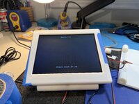
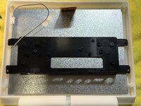
View attachment 24593

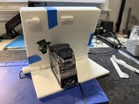
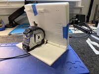
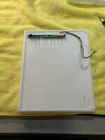
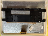
@wottle , one thing you will have to check is if the control panel buttons line up with the "back" of the LCD cover, it may need some adjustment. Most of these controller boards are very similar, but it might be just enough off to not fit correctly. There is currently no internal mounting holes for the video board itself, so you may have to resort to double-sided foam tape to hold the driver board to the back of the iPad screen. I will measure my board and add some mounts on the back panel for it before I print it.

My particular iPad driver only has VGA and HDMI inputs, no composite. My Eyoyo 8" has VGA, HDMI, and composite inputs.
View attachment 24594
I have the other revision that has composite video on, but I'm hoping the button control board is the same. But it does look like there are a bunch of different variants of the same controller boards. I even found this one which would be cool for my SE inspired LCD panel - a ton of inputs in an easily mountable form factor: https://www.ebay.com/itm/2269545937...eIs_Xj6R-FO4BRyoedhzPBtT9kiitqkVjgUKrHX1ZtRj4

I'm still hoping to squeeze in a buck converter off the USB-C trigger board so basically I'll have this:

Code:
                            /--- 15v ---> internal buck converter (12v) --- 12v ---> LCD board
---> USB-C Trigger (15v) -<
                            \--- 15v ---> external Apple IIc connector to power computer

So the LCD enclosure will have a single USB-C input for powering both the LCD and the Apple IIc, with two cables coming out (one going to power the IIc and one that has an RCA plug for composite video.

However, I actually checked the current being pulled for my 10" iPad screen off the monitor output line and it is pulling a bit over 400mA and I haven't run into problems. Given the 8" Eyoyo pulls less than that, I may go back to my original plan of having the pull power and composite from the video out port. That would allow me to have the LCD always plugged in with a single cable, and I could power the IIc from my usb-c power adapter. It achieves my main goal of not having to have multiple USB-C cables to power everything.
 
  • Like
Reactions: phunguss

phunguss

Active Tinkerer
Dec 24, 2023
480
412
63
57
Stillwater, MN
I have the other revision that has composite video on, but I'm hoping the button control board is the same. But it does look like there are a bunch of different variants of the same controller boards. I even found this one which would be cool for my SE inspired LCD panel - a ton of inputs in an easily mountable form factor: https://www.ebay.com/itm/2269545937...eIs_Xj6R-FO4BRyoedhzPBtT9kiitqkVjgUKrHX1ZtRj4
That board looks almost identical to my Eyoyo 8", minus the audio in/out.
eYoyo8.jpg
 

phunguss

Active Tinkerer
Dec 24, 2023
480
412
63
57
Stillwater, MN
I am going to need a bigger printer.

I was digging through my inventory looking for something else, when I stumbled upon an old iBook 14" panel with a controller board. It is wider than the iic !
iBook14-controller.jpg


Since I have the VGA output card for my //e, I think this one will get saved for that.
iBook14-measure.jpg


So much stuff, I forget what I have already.
 
  • Wow
Reactions: wottle

ArjenCNX

Tinkerer
Oct 20, 2025
35
30
18
you may want to upgrade the CCFL for an LED strip, they are cheap and available for 14" displays and will be brighter and save power
 
  • Like
Reactions: wottle

wottle

Active Tinkerer
Oct 30, 2021
814
563
93
48
Fort Mill, SC
I am going to need a bigger printer.

I was digging through my inventory looking for something else, when I stumbled upon an old iBook 14" panel with a controller board. It is wider than the iic !
View attachment 24615

Since I have the VGA output card for my //e, I think this one will get saved for that.
View attachment 24616

So much stuff, I forget what I have already.
That's why I had to create an inventory management system... I kept forgetting what I had and what I had done to each thing. I haven't cataloged all the random parts, though...
 

wottle

Active Tinkerer
Oct 30, 2021
814
563
93
48
Fort Mill, SC
So my JLC3DP order arrived!

Unfortunately, I didn't fully look at the instructions enough to realize that some of the parts need to be printed twice. Maybe in your instructions you could call out that there are two parts that need multiple prints (the knob and the cable hooks). Or maybe in the file names you can give them something that indicates they should be printed double (I see it now in your image, but missed it before).

Also, I think there may be a couple of parts missing that are probably optional, but you might want to include. It appears you have some small caps that go inside the slots on the knobs that cover the hex key when installed. I don't see those STL files or see them in your image of your prints. I'd like to make sure I have all the prints I need before I place my next order. I can't really complete this until I get the other knob, but trying to batch orders to save on shipping.

Also, there appears to be a support protruding from the bezel. I'm not sure if you put that there to level out the print to ensure the top surface will be as smooth as possible, or if I'm missing a hole on my back plate, but I assume I can cut this off?

IMG_9809.jpeg


Also, It seems like there's one channel for the cable under the base, but it splits out and there's a cable cover of some king for an offshoot. What's the purpose of that?
IMG_9810.jpeg


Finally, there are a couple areas that I think photos would be helpful for. First, I found the holes in the back for the USB-holder and cable hooks. I assume those are optional, but it would be good to show them installed so people know where they go. Second, maybe a picture of how the LCD control board, and the USB-C trigger board are mounted inside the case would be helpful. And third, related to the picture above, maybe something showing the cable routing of the RCA and USB-C cables would be nice. Not trying to be critical, just pointing out some things I struggled with trying to visualize how it all goes together. I can also take pictures of these things when I assemble mine, if you'd like.

This is awesome work and I can't wait to get started. I'll probably get the LCD and back panel set up with the LCD
 

phunguss

Active Tinkerer
Dec 24, 2023
480
412
63
57
Stillwater, MN
Also, there appears to be a support protruding from the bezel. I'm not sure if you put that there to level out the print to ensure the top surface will be as smooth as possible, or if I'm missing a hole on my back plate, but I assume I can cut this off?
I am not sure why that was so long, as there was not a matching hole in the back panel cover. Sorry my iPad version is taking so long... the CR10 large 3D printer I just bought needs some work.
CR10-fixing.jpg
I tried printing my design in quadrants on my smaller printer, to assemble with dovetails, but I was using some bad filament and it didn't work out. When I have the larger printer working, I will test it, and then upload my files.
A2CiPad-quads1.jpgA2CiPad-quads.jpg
 
Last edited:

wottle

Active Tinkerer
Oct 30, 2021
814
563
93
48
Fort Mill, SC
I am not sure why that was so long, as there was not a matching hold in the back panel cover. Sorry my iPad version is taking so long... the CR10 large 3D printer I just bought needs some work.
View attachment 24721
I tried printing my design in quadrants on my smaller printer, to assemble with dovetails, but I was using some bad filament and it didn't work out. When I have the larger printer working, I will test it, and then upload my files.
View attachment 24722View attachment 24723
No rush. I have the 8” to build so hopefully I can figure out the post and get the remaining parts ordered.

I also am a little unclear on the assemble of the knobs it appears you take a small Allen key and have to cut down both ends of the key to a specific length. The probably glue it into the knob? There’s a small lion holding the knob to the side, but it feels like the knob would not stay in place to tighten the hex head bolt. I’m hoping it will make more sense when I get the bolts and start assembly. I’ll also try to take assembly picture as I go.
 

ArjenCNX

Tinkerer
Oct 20, 2025
35
30
18
So my JLC3DP order arrived!

Unfortunately, I didn't fully look at the instructions enough to realize that some of the parts need to be printed twice. Maybe in your instructions you could call out that there are two parts that need multiple prints (the knob and the cable hooks). Or maybe in the file names you can give them something that indicates they should be printed double (I see it now in your image, but missed it before).

Also, I think there may be a couple of parts missing that are probably optional, but you might want to include. It appears you have some small caps that go inside the slots on the knobs that cover the hex key when installed. I don't see those STL files or see them in your image of your prints. I'd like to make sure I have all the prints I need before I place my next order. I can't really complete this until I get the other knob, but trying to batch orders to save on shipping.

Also, there appears to be a support protruding from the bezel. I'm not sure if you put that there to level out the print to ensure the top surface will be as smooth as possible, or if I'm missing a hole on my back plate, but I assume I can cut this off?

View attachment 24690

Also, It seems like there's one channel for the cable under the base, but it splits out and there's a cable cover of some king for an offshoot. What's the purpose of that? View attachment 24689


Finally, there are a couple areas that I think photos would be helpful for. First, I found the holes in the back for the USB-holder and cable hooks. I assume those are optional, but it would be good to show them installed so people know where they go. Second, maybe a picture of how the LCD control board, and the USB-C trigger board are mounted inside the case would be helpful. And third, related to the picture above, maybe something showing the cable routing of the RCA and USB-C cables would be nice. Not trying to be critical, just pointing out some things I struggled with trying to visualize how it all goes together. I can also take pictures of these things when I assemble mine, if you'd like.

This is awesome work and I can't wait to get started. I'll probably get the LCD and back panel set up with the LCD
Hi wottle, first of all, those prints look to be of good quality, so that is great!

1: the support on the bezel, is indeed a support, as this was intended for extrusion printing, its an extra help to make sure the print is levelled perfectly, quite important for extrusion printing, it can be removed, i think with your materials a dremel cutter is probably the safest option, second best is a small saw blade where you can manually remove it.
2: multiples, i agree, i could have been more clear, i did provide the prusa slicer pictures where you can see how many of each are printed, but it should probably have been spelled out. sorry about that, re-ordering is kind of shitty...

3: the cavity on the bottom side is where the USB-C PD PCB board goes, so you plug power in to the monitor there, i have glued mine in with hot-glue and then i filled it to make it flush. the main channel is where the video cable goes.

let me know how it goes with the inserts, i hope that will work out well.
 

ArjenCNX

Tinkerer
Oct 20, 2025
35
30
18
The Knobs i had i have drilled out slightly to get a tight fit, and then i pressed the allen key in the knobs, after cutting them to length, this may not be preferable for laser sintered material, it depends on it's brittleness, the allen key should be a tight fit so it not loose. it's a bit difficult for me to recommend on how to do this as i do not know exactly what materials you have there with your print. some experimentation may be needed there, so if you re-order, i suggest you get some extra's of this part.

if you have any other questions, please let me know, ill do my best to support you.

Hope it will be a great build!

Arjen.
No rush. I have the 8” to build so hopefully I can figure out the post and get the remaining parts ordered.

I also am a little unclear on the assemble of the knobs it appears you take a small Allen key and have to cut down both ends of the key to a specific length. The probably glue it into the knob? There’s a small lion holding the knob to the side, but it feels like the knob would not stay in place to tighten the hex head bolt. I’m hoping it will make more sense when I get the bolts and start assembly. I’ll also try to take assembly picture as I go.