Ladies and Gentlemen,
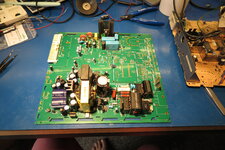
I have spent quite allot of time fixing Color Classic computers, and always there was that one Major issue: the analog board PCB quality.
Since it is a single sided FR-1 board with a super thin copper layer, populated with leaking capacitors this has presented myself, and probably you if you are reading this post, lots of issues over time.
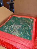
Thus, I have found a company that specializes in PCB design and had them re-create the original board, then I altered their single layer design in to a two layer design, to be made from FR-4 2 ounce copper PCB boards, selected all SMD parts, had them populated by JLCPCB so we have a fair shot of getting another 10 years out of our beloved Color Classics.
Work done so far:
- Created the layout of the PCB (Rev1.0)
- Created the Schematic of the analog board (Rev1.0)
- Created Bill of materials for all the components (the ones available, that is)
- Ordered PCB's with SMD parts (Rev1.0)
All this is done in the Free and opensource KiCAD software package, so anyone can chime in. The files recieved were in Altium, since I do not want to use closed-source software for this, I have converted this to KiCAD, this did introduce some discrepancies, not all of those are resolved at the moment.
My To-Do's:
- Populate PCB with through-hole parts
- Testing
- Getting your feedback
- Create next revision of PCB
- General clean-up of the schematic
Community affords:
I initially thought, ill just finish everything and test it and order new revisions, and get it all done before posting, but then I thought, that's just my ego talking, I should share it, ask you if your interested to help check the design, perhaps suggest improvements, make your own revisions, and so on because after all, that is what Tinkerdifferent is for!
So, I suggest we get to Rev.final together, most of the tedious stuff is done now and I would like your input on the current revision as I'm sure together we will be able to get a better end result if we can work together.
Community to-do's:
- Check current PCB design for mistakes
- Check current schematics for mistakes
- Check bill of materials
- Suggest improvements
- Build your own and test
- Hopefully someone will fork this and find alternate components that can still be bought, That's a long shot I know but it will be possible now.
Currently every part that is available has an LCSC part number, manufacturing part number.
So Happy tinkering everyone, hope you can chime in and for those willing and able, please help!
Arjen.