The board looks great, awesome work!Progress report:
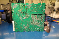
I have started to move parts from one of the original boards, since not all parts are in yet, and it seems a safer bet as to start with fresh parts (except for all electrolytic capacitors)
not done yet, but work is in progress!
once it's populated i will run a test to see if the power supplies work, before trying it out inside the color classic. ill keep you all posted!
Color Classic analog board re-design, needs community feedback.
- Thread starter ArjenCNX
- Start date
You are using an out of date browser. It may not display this or other websites correctly.
You should upgrade or use an alternative browser.
You should upgrade or use an alternative browser.
I'm about 95% done, and slightly nervous about the first power-up...
")
Well, got it all together, and on first power up the 5/12/-5 PSU side doesnt work, ill have to de-bug it to see what is holding it up. ill keep you posted on the progress
Well, got it all together, and on first power up the 5/12/-5 PSU side doesnt work, ill have to de-bug it to see what is holding it up. ill keep you posted on the progress
The amount of times I can count where I had issues with that PSU id be rich. I can say that I am not surprised, hopefully you iron it out.
Make sure standby voltage is making it to the TDA4605 via the opto circuit from the switchon stage.
Yeah, you got that right! so the HV supply switchmode is working, the +5 +12V one isnt starting through the power on command from the keyboard, im going to find out why that is, i do have the +5V from that HV switchmode side, and that is supposed to power up and activate the main PSU.The amount of times I can count where I had issues with that PSU id be rich. I can say that I am not surprised, hopefully you iron it out.
Make sure standby voltage is making it to the TDA4605 via the opto circuit from the switchon stage.
Okay, i have +5 and +12 aswell now, but when powering on, and when it's time to turn on the CRT i can see from my AC power meter it's doing a hickup thing where the power goes from 25 to 35W and back to 25W again. so i may have to measure the CRT PSU under load and do some fine adjustments.
Yeah, you got that right! so the HV supply switchmode is working, the +5 +12V one isnt starting through the power on command from the keyboard, im going to find out why that is, i do have the +5V from that HV switchmode side, and that is supposed to power up and activate the main PSU.
Yeah that HV side runs 24/7, thats why those zeners get baked out.
That transformer on the 520/550/575 has a slightly different winding ratio, they knocked that 24V tap down to around 18V and did away with the zener diode. They also bumped up the B+ winding.
Now i got all the voltages dialed in, i got the +5 / +12 / +8 / +24 / +60V / -5 all stable under load, but i still have a voltage drop over the 60V line on power up, and im not sure why that is yet. i also have RL28 getting hot, and that is also un-explained as of now, its a 2R2 1/2W resistor, right behind the Flyback transformer.
Sounds almost like it's in high-res mod mode, but I assume that's not really the case.still working on this, it seems my 60V is always too high at 80+V , the other voltages are in check, at 8 and 24V. quite strange to me. i have soldered up a new board now, but it is still not working as intended.
Have you looked at pot PP1? I don't think you can actually adjust the nominal B+ all the way up to 80V with PP1 alone, but it might be worth a look.still working on this, it seems my 60V is always too high at 80+V , the other voltages are in check, at 8 and 24V. quite strange to me. i have soldered up a new board now, but it is still not working as intended.
Thats only slightly high but its not too far off. It also needs to be under a load from the flyback producing HV before you can really measure it off.
Yeah, i know that as well, it seems complex as i have also used some cross-reference parts for several things, such as QL2, some diodes where i replaced them with slightly faster ones, while i cannot get the XC1186 main controller IC, or the LM2418 video amp IC. currently i have soldered up the second board, and have issues with the +5/+12V PSU, it will not activate when power is pressed on the keyboard, so ill have to go round to check the auxiliary +5 supply to see if it holds up, and the feedback to the opto-coupler there to turn it on. the fact that i cannot measure the underside of the board while it is in the housing and connected to the motherboard is not making things easier. even on my test setup the bottom of the board is hard to reach and with high voltages present one mistake could be quite memorable. ill struggle on here hoping ill get it up and running soon !Thats only slightly high but its not too far off. It also needs to be under a load from the flyback producing HV before you can really measure it off.
okay now i have checked the board one more time, and i cannot see any errors there anymore, i did fix 2 connections before, now i have measured the signal on the main transistor that drives the flyback, the unit responds to the power-on command, turns on, and as it is time for the flyback to activate i get a single spike on the Base pin of the Flyback transistor, and that is it, it will not start switching for some reason. I cannot find the XC1186B datasheet or equivalent anywhere, if anyone has any leads to this, i would appreciate it.
If HOT is not shorted and CRT PSU does not enter protection mode after it tried to start initially, then the fault might not be in the horizontal output stage.okay now i have checked the board one more time, and i cannot see any errors there anymore, i did fix 2 connections before, now i have measured the signal on the main transistor that drives the flyback, the unit responds to the power-on command, turns on, and as it is time for the flyback to activate i get a single spike on the Base pin of the Flyback transistor, and that is it, it will not start switching for some reason. I cannot find the XC1186B datasheet or equivalent anywhere, if anyone has any leads to this, i would appreciate it.
Did you check the main power supply and see if it works well under load? And +5V standby voltage? Also check POWER_SAVER signal coming from the logic board, this signal should be high and it should pull pin 41 and 42 high on XC1186B. If pin 41/42 are low, XC1186B won't output horizontal sync signal and there will be no high voltage.
So have 75V on the QL1, it is stable, oddly enough this is without the VGA mod in place, so it should be 60V or so. all other voltages are in check, Pin 41/42 have 5V on them, and the unit does attempt to start, this attempt doesn't last, and doesn't affect the 75V, it stays as is. i suspect there is a feedback line somewhere, and this behaviour could be related to the 60V beeing too high, however, i cannot understand why it is 75V at this point, im investigating this.
Also, thanks for chiming in, these things are more likely to be resolved if we can work together somehow, so if anyone else has ideas, suspicions, please chime in!
Also, thanks for chiming in, these things are more likely to be resolved if we can work together somehow, so if anyone else has ideas, suspicions, please chime in!
That's normal, unlike main power supply that has feedback control on the secondary, ctr power supply is regulated only on the primary side, it will fluctuate quite a bit as load changes. IIRC on standby +B is about 70-80V, so your reading is ok.So have 75V on the QL1, it is stable, oddly enough this is without the VGA mod in place, so it should be 60V or so. all other voltages are in check, Pin 41/42 have 5V on them, and the unit does attempt to start, this attempt doesn't last, and doesn't affect the 75V, it stays as is. i suspect there is a feedback line somewhere, and this behaviour could be related to the 60V beeing too high, however, i cannot understand why it is 75V at this point, im investigating this.
Also, thanks for chiming in, these things are more likely to be resolved if we can work together somehow, so if anyone else has ideas, suspicions, please chime in!
Don't think xc1186b has x-ray or +B protection mode, it works fine even after 84V VGA mod. Double check all secondary voltages on xc1186b and surrounding circuit, make sure they are within specs (24v, 8.3v and 5v). Trace the csync signal from logic board and see if it reaches xc1186b, if 41/42 are high and csync is present, it should output hsync and vsync signals, verify if they are present. If you have hsync output then there's something wrong with horizontal transistor driving circuit. Otherwise something's wrong with the xc1186b or it's surrounding circuit.
Also check out the reverse engineering of xc1186b on GitHub, it helped me a lot troubleshooting some stubborn color classic and lc575.
GitHub - jonschultz/colorclassic_video_processor: Project for the reverse-engineering of the Macintosh Color Classic's CRT video processor
Project for the reverse-engineering of the Macintosh Color Classic's CRT video processor - jonschultz/colorclassic_video_processor
 github.com
GOOD NEWS!
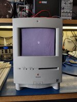
Thanks to mark_W, i found that i had the wrong value for DL1, the zener diode that protects in case of over voltage, once i placed it over from the orignal board, the unit started up and i have display now! still adjustments need to be done, geometry is not good yet, and neither is color, but im sure this can be adjusted/fixed!!!! Big day!
Thanks to mark_W, i found that i had the wrong value for DL1, the zener diode that protects in case of over voltage, once i placed it over from the orignal board, the unit started up and i have display now! still adjustments need to be done, geometry is not good yet, and neither is color, but im sure this can be adjusted/fixed!!!! Big day!