84V Mod on Color Classic - Thick light gray bars

surfer150

New Tinkerer
Aug 16, 2026
5
0
1
Hello together.

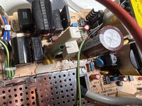
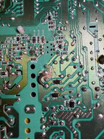
Mainly motivated by JDW’s excellent videos on YouTube, I decided to do the 84V VGA mod on my Color Classic too. To accomplish that, I cut the trace between pin 8 and pin 9, protected the copper with silicone (as i don’t have solder mask) and then connected pin 8 and pin 10 using a thick 1mm2 wire. Then I moved the 0 ohms resistor from J78 to J79. I ensured that nothing is shorted by taking measurements with my multimeter and compared the resistance of pin 8 and pin 10 with that of pin 8 to pin 9. I measured 0.05 Ohms vs. 0.25 Ohms.

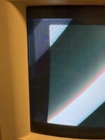
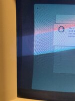
After powering it on with the stock logic board installed, I noticed a wide light gray (lit) border followed by a dark border. Also the picture is a little bit distorted as noticeable in the second and third picture.

It’s also noticeable that the light gray border moves up and down as well when turning the vertical trimmer on the back on the device. Also it’s wider on the upper side than on the lower side. If I turn the horizontal trimmer, the screen content of the OS moves from left to right but no changes in the bars. Is the cutoff set too high or is this another issue? I know that doing the VGA mod involves readjusting the tube but I want to ensure if this is really only an adjustment related issue.

Also I’m noticing a humming/whistling noise coming from the tube which was not there before i performed the mod.

The next step will be doing the beefy components upgrade next week and putting in a LC575 logic board once it arrives from Japan.
 

Attachments

  • IMG_4218.jpeg
    IMG_4218.jpeg
    1.4 MB · Views: 23
  • IMG_4212.jpeg
    IMG_4212.jpeg
    1.9 MB · Views: 24
  • IMG_4214.jpeg
    IMG_4214.jpeg
    2.8 MB · Views: 24
Last edited:

jonschultz

New Tinkerer
May 16, 2026
25
15
3
USA
github.com
Hi @surfer150, this is an easy fix. What you're seeing is that the G2 voltage (sort of like the black level control right at the tube) is too high and you're also starting to see "retrace lines". This is easily adjusted with the G2 potentiometer ("PL2 VG2"), on the left side of the analog board, just in front of the black heatsink for the horiztonal output transistor. You'll need a 2.5mm hex driver to make the adjustment. Just turn it down until the light grayish border disappears. This is a very commonly required adjustment any time something is changed with regard to the flyback transformer or B+ voltage. This grayish region will appear in any area that is actively being rastered because you're getting slight cathode emission when it's really supposed to be off. So it will move vertically with the "VS" control. The horizontal shift control doesn't actually change the position of the raster in the horizontal position, only where the video is traced in relation to it, and that's why the gray does not move with "HS".
 
  • Like
Reactions: surfer150

surfer150

New Tinkerer
Aug 16, 2026
5
0
1
Thank you very much. So my assumption was correct that it’s related to the adjustment called „cutoff“ in the service manual.

What about the humming noise coming from the tube? Is this normal? As mentioned, it was not there before the mod. At least not in that intensity.
 

jonschultz

New Tinkerer
May 16, 2026
25
15
3
USA
github.com
Thank you very much. So my assumption was correct that it’s related to the adjustment called „cutoff“ in the service manual.

What about the humming noise coming from the tube? Is this normal? As mentioned, it was not there before the mod. At least not in that intensity.
This might simply be from the horizontal deflection (refresh) now running at 67Hz instead of 60Hz, and there just happens to me more resonance. The coils change shape ever so slightly and vibrate from the large deflection currents, and the vertical frequency is low enough to detect audibly. I’m not sure if you will have other resolutions/refresh rates as options in the “Monitors” control panel, but you could try those if so and see if you notice any difference.
 

Mark_W

Tinkerer
Feb 2, 2026
39
29
18
Agree with what @jonschultz said before regarding B2 voltage. Also first thing you need to do before adjusting geometry is to adjust the trimmer PP1 near the crt power supply and make sure you get 8.3V/24V/84V on secondary outputs, you can use test points labeled TP1/TP2/TP3. Usually when you do the VGA/Hi-res mod the loading on the secondary changes and voltage output drifts off, which will change all geometry and color settings as they depend on 8.3V and 24V. If PP1 is glued you need to replace it, it's a 1k trimmer iirc.

If you still get thick boarder after adjusting voltage, you can play with CL26 on the back of horizontal output transistor to increase horizontal width. The capacitor may not be installed from factory. You need high voltage ceramic capacitors rated a few nF, start with 2.2nF or 3nF. Image width should increase with CL26 capacitance.
 

surfer150

New Tinkerer
Aug 16, 2026
5
0
1
PP1 is not glued on my revision B board, but how to adjust it when the tube is just above the trimmer? I can’t get to it without the risk of touching the yoke or other high voltage components.

I’m assuming I must get these voltages under load? But how to measure the test points with the analog board mounted in? They are on the back of the AB.
 

Mark_W

Tinkerer
Feb 2, 2026
39
29
18
Yeah it's kinda tricky to do it with analog board installed, what I did is measure voltage, pull analog board out, make very small adjustment, install analog board, measure voltage again, repeat a few times and you can get the voltage spot on. For glued pp1 i just replace them with precision trimmer installed at an angle so i can adjust it with a long screw driver. For measurement you can use horizontal output transistor center pin, it should be +B voltage (84V) iirc. For 8.3V and 24V you can measure them on xc1186 jungle ic, or just solder wires to those test points.

Btw if you haven't recapped the analog board yet, do it now. As a side note for component upgrade (zener diodes and power resistors), it's not directly required by the VGA/Hi-res mod, as the regulated 18V/8.4V only drives jungle ic and some geometry correction circuits, but due to the design flaw (insufficient rating, airflow and CRT power supply runs constantly even when power is off) DL21/22 will burn out eventually and cook surrounding capacitors to death.
 

surfer150

New Tinkerer
Aug 16, 2026
5
0
1
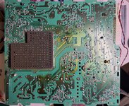
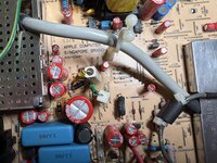
I did the beefy component upgrade today. Beside of replacing the parts JDW recommends to replace, I used the opportunity to replace a few more resistors which created burn marks on the PCB too, like the ones near the mains input (with 11W ones). As the soldering pads released because of the excessive heat, I applied a bit glue on the components side and silicone on the soldering side to hold that heavy components in place.

Will test it and measure the voltages tomorrow once the glue is cured.

Is it required to measure all three voltages? Is it not sufficient to set the voltage on the middle leg of the horizontal output transistor to 84V? I want to avoid to do any additional soldering jobs on this board as the pads easily release.
 

Attachments

  • IMG_4229.jpeg
    IMG_4229.jpeg
    3.2 MB · Views: 7
  • IMG_4231.jpeg
    IMG_4231.jpeg
    1.5 MB · Views: 8
  • IMG_4232.jpeg
    IMG_4232.jpeg
    1.5 MB · Views: 7
  • IMG_4230.jpeg
    IMG_4230.jpeg
    2.2 MB · Views: 8
Last edited:

Mark_W

Tinkerer
Feb 2, 2026
39
29
18
Not necessarily since all 3 voltages come from the same transformer and they are tied together. I just measure them to confirm the other 2 voltages aren't too out of spec, otherwise there might be some issue with the transformer.

As for damaged trace that's normal, every single CC I've dealt with have this problem on DL21/22 where the copper trace peels off the PCB with little force. That's due to the heat DL21/22 generates over the years. On one board DL21/22 even cooked the underneath PCB to a black char and I can poke through it easily, needless to say all traces underneath are ruined and I had to bridge everything with resistor legs.
 

surfer150

New Tinkerer
Aug 16, 2026
5
0
1
Sure but the most dramatic damage on my board was underneath the both resistors near the mains input. That’s why I replaced them with 11W types.