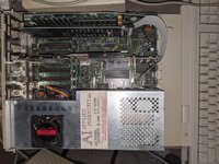
Does anyone know the wiring for the CPU ribbon cable that connects a TransWarp GS card to the original CPU socket on a IIgs mainboard? It's a 40-pin connection on the TransWarp card, I'm just wondering whether there's a published diagram for insertion into the DIP socket at the other end. Wouldn't want to wire up anything wrong.
Assemble a TransWarp GS CPU cable?
- Thread starter @GamesMissed
- Start date
You are using an out of date browser. It may not display this or other websites correctly.
You should upgrade or use an alternative browser.
You should upgrade or use an alternative browser.
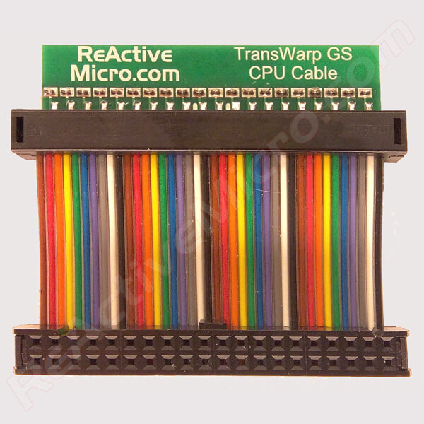
If you don't want to try to make it, you can buy it from ReactiveMicro:
 www.reactivemicro.com
TransWarp GS CPU Cable
As most TransWarp GS owners already know, the board does not use a standard 'straight through' CPU Cable. Our unique design addresses this by using a small PCB to allow for lower cost and better relia
www.reactivemicro.com
Thank you, all. I was hoping it was relatively straightforward (well, as straightforward as a IIgs processor upgrade card might be). So far, I've been looking at this page, mapping the pinout of the processor socket on the TransWarp GS card to the 40-pin socket for the cable to connect to the IIgs logic board, and then at the Western Design Center datasheet for the processor line. It feels like all of this together should be enough to build the cable. I'll post of any further progress.
Yup. But that, combined with the datasheet for the processors, should be enough for me to start.That website has the pinout for the top connector, not the main CPU socket.
As stated on several sites, the wire pairs need to be flipped similar to this example.