Breaking the 36MB RAM limit on the LCIII

max1zzz

Moderator
Staff member
Sep 23, 2021
232
549
93
27
Normally the LCIII is limited to 36MB of RAM - 4MB onboard and one 32MB SIMM
The simms are limited to 32MB as there are only 11 address lines hooked up to the RAM SIMM socked so larger sticks won't work (The will typically show up as 16 or 32MB)

However while creating a pin listing for the Sonora ASIC at the heart of the LCIII I noticed something interesting - there where two signals leaving the Sonora which went to two resistor packs on the underside of the board but went nowhere after that, everything else going through these resistor packs where RAM signals so maybe there where RAM signals too? Maybe they where two additional RAS signals and at some point Apple had considered designing a LCIII with two SIMM slots?

A little probing with the oscilloscope revealed a signal that to my untrained eye looked a lot like a RAS signal on both of these

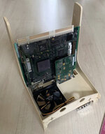
There was only one thing for it, bodge a second SIMM slot in!
IMG_2100.jpg


All signals between the two SIMM slots are commend except the RAS signals for which the external slot is connected to the extra RAS signals I found on the board

The result (after one extremely long memory check) was this:
IMG_2099.jpg

52MB :)
Thats 4MB onboard + 16MB in one slot and 32MB in the other

Why not 2 32MB simms? I could only find one working 32Mb simm :)
I did once get a second very flaky 32MB simm to play ball for long enough the get the LCIII to boot and report 68MB total but didn't get a picture of it....

Want to try this craziness yourself? the two extra RAS signals can be found on pin 14 of RP4 and pin 16 of RP5

It not currently very practical as there isn't exactly anywhere to put a second slot on the LCIII but I do have the idea of creating a RAM upgrade board for the LCIII that plugs into the simm socket and picks up the additional RAS signals with flying wires (Essentially cramming two RAM simms into one)

It should also in theory be possible to replace the on-board bank with 16MB giving a total possible maximum of 80MB, more than 2x what apple says is supported!
 

YMK

Active Tinkerer
Nov 8, 2021
345
266
63
As I commented on MLA, this is very exciting! Frankly, I would accept a special cable that connects one end to the board and the other to a loose RAM slot... :D

It would just be a single DIMM installed in the factory slot that needs a couple of wires soldered to the logic board.
 

max1zzz

Moderator
Staff member
Sep 23, 2021
232
549
93
27
As I commented on MLA, this is very exciting! Frankly, I would accept a special cable that connects one end to the board and the other to a loose RAM slot... :D
This is one of the approaches I'm looking in to, just as long as there is actually space somewhere in the LC III to stuff the other simm slot
 
  • Like
Reactions: lilliputian

Kai Robinson

TinkerDifferent Board President 2023
Staff member
Founder
Sep 2, 2021
1,032
1
1,065
113
41
Worthing, UK
Custom bracket for the hard disk bay, mount a bluescsi and a new RAM slot in there, os that too far for signal traces?
 

max1zzz

Moderator
Staff member
Sep 23, 2021
232
549
93
27
Custom bracket for the hard disk bay, mount a bluescsi and a new RAM slot in there, os that too far for signal traces?
Funnily enough that was pretty much my initial idea, but I don't know if the signal trace length would be a issue

I'm taking the approach of making a breakout SIMM that has connectors that can be plugged into either a RAM card or a riser module as this allows for flexibility of exactly what is connected as well as where the expansion board is located in the chassis

This breakout SIMM to be exact:
22-05-22.JPG


Just need to design the RAM card and SIMM riser to go with it :)
 

Trash80toG4

Tinkerer
Apr 1, 2022
779
242
43
Bermuda Triangle, NC USA
Very cool. Love your incredible research results.

I've had some trouble describing this setup to you in words, so did a sketch this morning. Don't know if it'll fit in the LCIII, but Quadra project might be worth a look? SIMMspender is the inverse of a SIMMsaver. It consists of a passive TwinSlot implementation.

Q605-Q630-SIMMspender-2022-00.JPG


The sockets are flip-flopped, so CAS/RAS/Address traces make a turn in the opposite direction. Half of the data lines will require remapping in 16bit chunks on left and right sides of the adapter. That's a simple thing that the controller shouldn't even notice has been done. Worst case would be reversing the entire 32bit Data Bus as needs to be done to the IIci Cache Slot for PowerCache adaptation on the SE/30 PDS.

At any rate, this might work for your pair of SIMM slots? The passive SIMM adapter would remain in place if flying wires are directly soldered. Headers or sockets implemented on the adapter would support breadboard wires allowing disconnect for removal. You can always remove it for baseline system function in either case.

If this'll fit in the LCIII it should simplify things significantly? Whatcha think?
 
Last edited:
  • Like
Reactions: -SE40-

max1zzz

Moderator
Staff member
Sep 23, 2021
232
549
93
27
Interesting, I hadn't thought of doing it that way......
I'll need to do some measuring to be sure weather or not that would fit
I suspect the floppy and power connectors might get in the way of the backwards facing simm's but i'll need to double check that
 

YMK

Active Tinkerer
Nov 8, 2021
345
266
63
How about 45 degree sockets so that the memory is parallel to the logic board?
 

Trash80toG4

Tinkerer
Apr 1, 2022
779
242
43
Bermuda Triangle, NC USA
SIMMsppender can be extended to left or right using a modified 72pin form factor. ;)

OMG, I so wish I had my Quadra 630 board to do this. It should have the full memory ceiling, greater than the two SIMM Slotted DOS boards when I get done with it. 🤪
 

Trash80toG4

Tinkerer
Apr 1, 2022
779
242
43
Bermuda Triangle, NC USA
Got a pic? My LCIII is out on loan . . . forever it seems. :(

Quadra 630 project predates Section 8 AWOL MIA period and Quadra 605 riff was after I popped back in, but predates general availability of filimant printing technology. Switching the design up for SMT bodge of SIMMs/Adapter combined with printed. boltup support structure should be rock solid:

SMT-SIMMspender-Printed-Carrier-00.JPG


Elimination of thruhole SIMM Sockets frees up entire adapter for flip-flop trace implementation save for the two rows of 72 solder pads. It's not AI playtime, but half-assed mechanical sketching is good therapy. I'm home from work in mental health maintenance mode. Came home early yesterday with as close (not very) to a psychotic break as I've had since last trip to the hospital.

Maybe TMI, but my being open about this has led to help for others both IRL and in the Virtual World. Tool time and artwork rock! Take care of yourselves gang, a mind is a terrible thing to lose and Psychopharmaceuticals are a gift from on high. :)
 
Last edited:
  • Like
Reactions: YMK

-SE40-

Tinkerer
Apr 30, 2022
416
161
43
The Netherlands
pin.it
Interresting solution…..
I love to try this out on my 630 (SE40) project.

Would it be possibe to cut a slot in the PCB and slide the sim in and so lock in together with the 3D printed part?
No stress on the solder joint as a result.
 

Trash80toG4

Tinkerer
Apr 1, 2022
779
242
43
Bermuda Triangle, NC USA
Thanks, it's been a long time coming! No need for slotting in config above, or maybe I don't understand your question?

I've been looking for my SIMMspender project box to no avail, but I just developed a suspicion about where it might be now that I stopped thinking about it. I have one very complex active component, four slot SIMM Saver or Expander on my desk, but it's too complex for illustrative purposes. Maybe later?

Curious, got linkage to your project?
 

-SE40-

Tinkerer
Apr 30, 2022
416
161
43
The Netherlands
pin.it
Just a quick edit, but again thinking about this idea….it may break traces to the top sim.
F3364F6F-CAF4-4793-9AE3-EEA2411A8CF6.jpeg

As for my SE40 project, do check the pinterest link in my profile for more pictures.
 

Attachments

  • D56C47DF-EAF0-4DDC-9CAC-AF60CC080094.jpeg
    D56C47DF-EAF0-4DDC-9CAC-AF60CC080094.jpeg
    152.5 KB · Views: 101

Trash80toG4

Tinkerer
Apr 1, 2022
779
242
43
Bermuda Triangle, NC USA
No worries about breaking the solder joints, the printed supports would be installed before soldering with good contact. Mounting screws are smaller diameter than the holes in the SIMM's for finagle factor. Holes in SIMMs can be drilled out to larger diameter if necessary or advisable overall from the start? After the fact crowns of epoxy can be added to screws as well. ;)

Edges of Simms can be filed to the 45 degree profile of the adapter so top and bottom edgecard teeth make good or close contact with their SMT pads for flux and flow of solder. Bottom SIMM installed first. If reliability is an issue, the SMT pads can be elongated so it after flux and flow is accomplished, it would be very simple to reflow bent copper wires with a poke of the iron and topside excess clipped.

My soldering skill leave most everything to be desired, stone age prototyping, wire wrapping knuckle dragger here. 🤪

I'll do another rough sketch in isometric of the joint details later, should be fun! :)
 
Last edited:

Trash80toG4

Tinkerer
Apr 1, 2022
779
242
43
Bermuda Triangle, NC USA
Just noticed I ran the SIMMs right through the adapter in that sketch. OOPSIE! :oops:

edit: just checked, I didn't do that, did you edit it like that?

< tangent >

Cool looking setup for the -SE40- are you planning an LCD? All I saw was that one pic. If you wanna wade through some awful .TXT description with links to every single picture busted, Have at it. Some of the craziness could apply to your configuration. My Classic has two PCI slots. ;)


If you'd like to collaborate, start up a new hardware topic and I'll run down some pics or take a few new ones.

< /tangent >
 
Last edited: