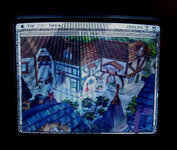
Color Classic analog board trouble

YMK

Active Tinkerer
Nov 8, 2021
358
285
63
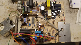
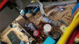
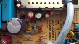
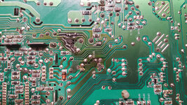
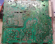
When I got this machine, the logic board had been fully recapped and the analog board partially recapped. The display and soft power both worked, but the picture was pinched horizontally in the middle, like an hourglass. The DL21 and DL22 18V zeners were cooked and burned the PCB around them. I replaced them both with 1N4746 and changed the rest of the AB caps, except for the ones in the shielded cage. RL62 was cooked and open and I replaced it with a metal film 47Ω resistor.

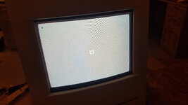
Now when I turn on the rocker switch, the machine starts immediately (no soft start), chimes normally, but there is no picture. There is high frequency noise in short chirps, at about 3 per second, as if the AB is trying to start the display, but can't. The neck of the tube is not glowing.

I've confirmed cap polarity repeatedly and the newly installed parts don't appear to be under distress. No smoke, smells or noises.

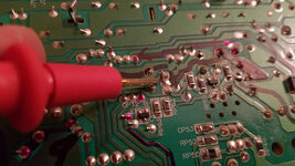
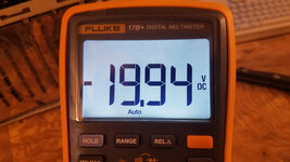
I measured 47.5V at the center pin of the horizontal output transistor, but I'm not sure if this is the right place to get the B+ rail.

Out-of-circuit measurements:
RF11: 363Ω
RL62: 48Ω
RF8: 1.4Ω
RL22: 100Ω
RF19: 4.7Ω
DF2: Not shorted

Running measurements:
12V Rail: 11.6V
5V Rail: 4.9V
Center pin of horizontal output transistor: 47.5V

Some questions:
Is RL62 47Ω? My old part was too damaged to read so I replaced it based on the parts list below.
What type of diode is DF2?
What is the role of the DL21 and DL22 18V zeners? They are not populated on the LC575 AB.
Which components are involved in generating the B+ rail?
Where is the best place to measure B+?

Any help or documentation is greatly appreciated. I did find this parts list:
I've also attached it (html renamed to txt) since most CC resources seem to have disappeared.
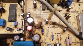
20230213_235519.jpg20230213_235802.jpg20230213_235814.jpg20230213_235834.jpg

Thanks.
@JDW @Kay K.M.Mods
 

Attachments

  • CC Analogue Board Master Parts List.txt
    37.2 KB · Views: 106
Last edited:
  • Wow
Reactions: JDW

JDW

Administrator
Staff member
Founder
Sep 2, 2021
1,577
1,373
113
53
Japan
youtube.com
I downloaded the attachment in the opening post, but I needed to change the extension from .txt to .html and then I could view it. Nice info!

I spoke with Kay Koba, who is truly my Sensei about all things related to the CC, and he is unsure about the root cause. He is concerned about the extent of the burning. So am I. It's clear the voltage regulator must be working, otherwise you would not have been able to measure anything close to 12V or 5V.

The issue here is what caused the burning in the first place:

1. Simple failure of one of the components in that area which lead to others burning?
2. Failure of another component which caused a high current draw in the burned area?

The fact you swapped out the burned components with good versions and still get nothing indicates the root problem must be outside the burned area. I say that because it seems your trace repair was good, so that cannot be the issue.

Hmmm...
 
  • Like
Reactions: retr01 and YMK

YMK

Active Tinkerer
Nov 8, 2021
358
285
63
The issue here is what caused the burning in the first place:

1. Simple failure of one of the components in that area which lead to others burning?
2. Failure of another component which caused a high current draw in the burned area?

DL21 and DL22 burning up seems to be a common problem and pictures of other boards look similarly damaged to mine. These are two zeners in parallel in the same direction, for the apparent purpose of sharing the load, which isn't a great design. With or without the replacement parts, the behavior is the same.

It's clear the voltage regulator must be working, otherwise you would not have been able to measure anything close to 12V or 5V.

The low voltage rails are fine, other than soft power not working anymore. If the 47.5V I measured is the horizontal voltage, then it's too low and I need to figure out where it comes from.
 

YMK

Active Tinkerer
Nov 8, 2021
358
285
63
I now have soft power and a picture! :)

I found a tiny solder shaving bridging two pins on IP11. I don't think I reflowed it during the course of the recap but removing the shaving did the trick.


20230215_013221.jpg

The hourglass distortion is now gone, but I noticed some occasional flickering which coincided with arcing sounds so the flyback may have problems.

20230215_013753.jpg

I'm keeping an eye on voltage across the zeners. There's a good chance they burn out like the originals did. I'll find a single replacement with a higher rating.

20230215_013837.jpg

This video by @techknight was helpful for making sense of the board.


My understanding is a 24V input is current limited by a resistor, then clamped by the 18V zeners (which are absent on the LC575). I'm not sure what the output of this circuit modulates though.
 

JDW

Administrator
Staff member
Founder
Sep 2, 2021
1,577
1,373
113
53
Japan
youtube.com
I am quite curious about Soft-power having worked originally when you got your hands on that CC, but then after recapping, you said the machine powers on immediately by the mere flip of the switch on back (which should not happen).

We know that soft-power is merely the grounding of pin-2 of the ADB connection, as per this diagram...

1676595506481.png


Something must be pulling pin-2 (normally a HI +5V logic level) to GND for the minimum required duration of what I believe is 200ms or longer. Have you probed that area of the circuit?
 
  • Like
Reactions: YMK

YMK

Active Tinkerer
Nov 8, 2021
358
285
63
Have you probed that area of the circuit?

It turned out to be a shaving of solder bridging the pins of a transistor. After fixing that, soft power worked again and so did the display. B+ voltage increased from 45V to 60V under load.

I then tried to adjust the display using the rear pots, but when I did, RL62 began smoking. I shut down power immediately and replaced the single 47Ω resistor with four in a series/parallel arrangement for increased power handling. I also swapped DL21 and DL22 with a string of 1N4001 for the same reason. That bought me enough time to properly adjust the display.

I also tried to reduce B+ voltage by adjusting the PP1 potentiometer, but it was glued to prevent tampering. I wasn't able to remove the glue without ruining the pot, so I swapped in the one from my LC575 board. That one was not glued. I'll have to order another 1K pot to replace it.

I think these parts are underrated for the power they're subjected to and having the display out of adjustment seems to stress them further. It might explain why I see the same parts burning up on other boards.

kq5.jpg
 
  • Love
Reactions: JDW

JDW

Administrator
Staff member
Founder
Sep 2, 2021
1,577
1,373
113
53
Japan
youtube.com
Wow! So it looks like things are working now. And all because of a tiny shaving of solder!

But can you show me where in your photos RL62 is located? I Googled up other CC analog board photos but can't seem to find it inside the shielded cage. (And I don't have my CC open in front of me to check.)

And when you said RL62 began smoking, that your new, metal-film replacement of the same wattage rating as the stock resistor, right?

The only scorched area on my CC's analog board is the PCB under these two diodes...

1676608458554.png


Those same diodes also charred the PCB underneath in this photo by @Branchus ...

1676608609707.png


And the resistor I marked with a red arrow in his photo also seems to have overheated.
 

YMK

Active Tinkerer
Nov 8, 2021
358
285
63
This was my RL62 before it went up in smoke. The four that replaced it are still holding up:

1676611389285.png
 
  • Love
Reactions: JDW

JDW

Administrator
Staff member
Founder
Sep 2, 2021
1,577
1,373
113
53
Japan
youtube.com
Thank you!

Very interesting that your blue, 1W-rated replacement also burned. So by saying "4" you mean you have the equivalent of a 4W resistor in there now?
 

JDW

Administrator
Staff member
Founder
Sep 2, 2021
1,577
1,373
113
53
Japan
youtube.com
Out-of-circuit measurements:
RL62: 48Ω
Some questions:
Is RL62 47Ω?

Just wanted to add further clarification to this thread, since some questions in the opening post were never answered, and people finding this thread over time may have the same questions. Yes, RL62 is 47Ω. But tolerance seems to vary.

In your photo, the stripes, from right to left, look like: YELLOW, GRAY, BLACK, GOLD, BROWN

1679984895799.png


But "GRAY" can't be right because in photos of my own board and that from Bruce, we see that "gray" stripe is in fact "purple," which means it is a 47Ω resistor. But even if GRAY was right on your board, that would make it 48Ω, which is only 1Ω higher than the resistor on my board and that of Bruce.

1679984993195.png
1679985020426.png


Even so, your RL62 has 5 stripes which means it is a 47Ω 1% resistor (assuming that GRAY looking stripe to be PURPLE), but the resistors from my board and that of Bruce have a 5% tolerance as per the fact there are 4 stripes and the 4th is gold.

It's hard to find 1% tolerance high wattage resistors, but I think 5% should be fine, in which case, this 3W resistor might be a suitable replacement, for people who don't want to solder 4pcs of a 1W 47Ω in there:


What type of diode is DF2?

I haven't broken apart my CC to have a better view of the markings, and I can't see the markings in my photo of that of Bruce. Were you able to see the markings?

It really would be nice to have a CC Analog Board schematic to answer the remaining questions.


You are correct about two Zener diodes in parallel being a bad idea. The following Toshiba page explains why:

Were you able to read the part numbers on the DL21 & DL22 to determine if the factory parts are 500mW or 1W or something else? Yours look like glass encased Zeners which I suspect are 500mW. The black bodied parts used on my board and Bruce's board could be 500mW too or maybe even 1W, but again, I would need to know the part numbers to know for sure.

If both are 1W, then it perhaps could be that putting a single Zener of 2W would work fine. Or you could double the wattage and put two in there. Then if one burns, due to most of the current going through it, the second one would be fall-back to keep the circuit going. However, when you choose a higher wattage Zener, it takes more current for the higher wattage zener to achieve its rated voltage, versus the lower wattage Zener. That means the voltage will rise higher with the higher wattage Zener. And without a schematic, I cannot say if that marginally higher voltage would spell disaster or not. There are some who disapprove of using higher wattage Zeners as replacements, and there is merit to that argument...


It may be best to replace the Zeners with the stock part number and just raise them on their legs to achieve better cooling.

With that said, you mentioned using "a string of 1N4001" as a replacement for DL21 & DL22. How many 1N4001 diodes did you put in series?
 
  • Like
Reactions: YMK

YMK

Active Tinkerer
Nov 8, 2021
358
285
63
The original RL62 on my board was burned beyond recognition, so I replaced it with this (as pictured), then later four of them:


I got that p/n from my order history, so I'll have to find the bag to confirm the stripe colors.

I later swapped in this 5W resistor: https://www.amazon.com/dp/B0BN85F42S
and replaced the two Zeners with one of these 5W parts (1N5355): https://www.amazon.com/dp/B09NSQ3PD2

Both replacements are holding up well.

How many 1N4001 diodes did you put in series?

25 in the opposite direction of the original Zeners. This was a stopgap measure until the Amazon parts above arrived. DL21 and DL22 on my board were too damaged to identify.
 
Last edited:
  • Love
Reactions: JDW

YMK

Active Tinkerer
Nov 8, 2021
358
285
63
However, when you choose a higher wattage Zener, it takes more current for the higher wattage zener to achieve its rated voltage, versus the lower wattage Zener. That means the voltage will rise higher with the higher wattage Zener. And without a schematic, I cannot say if that marginally higher voltage would spell disaster or not. There are some who disapprove of using higher wattage Zeners as replacements, and there is merit to that argument...

The 1N5355 is rated: Vz = 18V at 65mA, or 1.17W.

If the higher wattage part requires more current to hit 18V, installing it in a (mostly) fixed current circuit should result in a lower voltage.

Given how steep the I/V plot is around Vz, I don't expect much difference, though I didn't measure the stock parts under load.
 
  • Like
Reactions: JDW

JDW

Administrator
Staff member
Founder
Sep 2, 2021
1,577
1,373
113
53
Japan
youtube.com
I personally think most CC owners should swap out those two Zeners because every single Analog Board I've see has scorch marks on the PCB underneath them. And even if the stock Zeners are still working, I'd feel better to raise them up on their legs at least 1cm off the PCB for better airflow around them, but you can't do that with the stock parts because the legs are cut short. So you would have to replace them.

I hesitated to consider a 5W Zener as a replacement for the reasons you and I are discussing, but clearly in your case, there hasn't been any ill effects, so I guess using two 1N5355's really is a good choice. And replacing RL62 with a 3W or 5W version 47Ω resistor is a good idea as well.

Whenever I find the time, I would like to go back and change my VGA mod to the higher 84V version so as to regain compatibility with the stock motherboard. That should also allow the LC520 motherboard to work too, and one of those recently fell into my hands. I also am itching to try my TechStep cartridge which works with the stock CC motherboard, to see how it functions. But I avoided doing that version VGA mod only because I was scared by the warnings of it being harder on the Analog Board. But by strengthening some of the components which are known to burn by way of properly chosen replacements, perhaps we could avoid catastrophe, especially when the spinner drive is swapped out for MacSD or similar.
 

YMK

Active Tinkerer
Nov 8, 2021
358
285
63
so I guess using two 1N5355's really is a good choice.

I'm only using one. Both the Zener and 5W resistor are elevated from the board. I agree it's good for cooling.

But I avoided doing that version VGA mod only because I was scared by the warnings of it being harder on the Analog Board.

I don't know what the common failure modes are with 84V. The active components might benefit from better heatsinks.
 
  • Like
Reactions: JDW

JDW

Administrator
Staff member
Founder
Sep 2, 2021
1,577
1,373
113
53
Japan
youtube.com
I'm only using one.
Thank you for that clarification!

I don't know what the common failure modes are with 84V. The active components might benefit from better heatsinks.
When I made my VGA mod video, I spent a lot of time researching the matter because there was a fair amount of incorrect or misleading info out there on the web. Even in the Doping Mac book mentioned in my video, I found a small error. And while the info about the 84V version mod is fairly consistent about it being "harder on the analog board," most of that is copy/paste from something said more than 20 years ago. It is logically that a higher voltage would result in more current flow and therefore more heat, and heat does kill. But aside from that talk, we don't see any hard facts about failures or which components get much hotter.

If I had a Flir or similar, it would use my iPhone to check the heat of all the components when the standard VGA mod is running. One can then take an educated guess on which of those hottest components would be even hotter with the 84V VGA mod, and then consider how best to cool them. It could be that a fan mounted on the analog board and blowing across components would be all that is needed.
 
  • Like
Reactions: Paolo B

JDW

Administrator
Staff member
Founder
Sep 2, 2021
1,577
1,373
113
53
Japan
youtube.com
I assume you swapped out your burned RF11 as well, because it looks quite burned indeed...

1680079005991.png


On my board it looks like this...

1680079054528.png


Looks like RED, YEL, BLK, BRN, but BRN must be GOLD. But RED, YEL, BLK, GLD = 24Ω, which can't be right.

If we say it is ORG, YEL, BLK, GLD, that is only 34Ω, which can't be right.

ORG, WHT, BLK, GLD = 39Ω, which can't be right

ORG, YEL, BRN, GLD = 340Ω, which could be right.

ORG, WHT, BRN, GLD = 390Ω, which sounds right based on what I found below.

On this video by @Branchus , Bruce says it is 390Ω...

1680079277987.png


But what befuddles me is what looks to be a wire wrapped right across the resistor in my photo above. And I can sort of see that in the photo by @Branchus too, wrapped across the right side leg anyway...

1680079478707.png


Not sure what that is because I don't have my CC torn apart in front of me.

Anyway, I assume you used a 5W 390Ω replacement for RF11?

By the way, if you keep watching that video by Bruce, I can see 1N 52 markings on DF2, but I can't read the rest.
 
  • Like
Reactions: YMK

JDW

Administrator
Staff member
Founder
Sep 2, 2021
1,577
1,373
113
53
Japan
youtube.com
Another thing that has me baffled is why there is hot-glue only on that RF11 resistor. There are a number of raised resistors on the board, but they don't have hot glue on them. What is so special about RF11 that necessitated hot glue? Hmmm...
 

YMK

Active Tinkerer
Nov 8, 2021
358
285
63
I left RF11 alone for now because it measured 363Ω. The discoloration looks like it may have come from the outside.

1680193283299.png

I've picked up another CC AB in better condition. You can see the diodes are in better shape, but still scorching the board:

1680194031589.png

I can now identify DF2 (1N5237B), which was not present in the parts list I posted above.

This board also has (part of) the "wire" wrapping the resistor you mentioned, but it doesn't seem to be conductive. Maybe it's some remnant of the packaging?


If I had a Flir or similar, it would use my iPhone to check the heat of all the components when the standard VGA mod is running. One can then take an educated guess on which of those hottest components would be even hotter with the 84V VGA mod, and then consider how best to cool them. It could be that a fan mounted on the analog board and blowing across components would be all that is needed.

I do have one of those...

1680194883553.png


The oversize RL62 isn't too hot, but the stock RL22 at 167C might be an upgrade candidate as well.

Fortunately, these flybacks don't seem to run as hot as the monochrome compacts:

1680195105779.png


I will probably upgrade the horizontal output heatsinks on both boards whether I attempt 84V or not. Here, it's running 640x480 at 71.9V.
 
  • Love
  • Like
Reactions: Redsward and JDW