After my 84V mod (640x480), the heat of the 18V 5W Zener used at DL22 caused me a lot of lost sleep. I just wasn't satisfied with the heat it put off. After some in-depth study, it seems the way these Zeners keep cool is to dump all their heat into the legs, which is why the two stock Zeners where mounted right against the board, rather than being stood up on their legs. The higher you raise these Zeners, the worse the heat dissipation becomes, UNLESS one or both legs in soldered into a heatsink. If you look at the SE or SE/30 Analog Board and examine the side of the Flyback cage facing the bipolar capacitor, you will see one diode has a leg soldered to the metal cage for heat sinking reasons.
When I made
my BEEFY UPGRADE video, I didn't want to use my
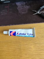
100% copper alligator clips (affiliate link) for fear they might fall off and cause a short. But after much thought, I decided to cut the alligator clips in half and solder one of the halves to either side of the Zener. Not only that, but I bought a physically larger
DO-201 package size Zener diode with the same
1N5355B part number:
The legs on that DO-201 edition Zener are thicker than the smaller DO-15 5W Zener I had been using, and the thicker legs are why I've not updated my Mouser cart to use that DO-201 version instead. I don't think most people would be willing to do the work I did to install it. But I want to write this report for those of you who do wish to follow my lead in the quest for a much cooler running 18V Zener on your CC Analog Board. As such,
I recommend most people add the DO-201 diode above to their preferred Cart below, and that way you can decide which 18V Zener you want to use (going with the DO-201 if you don't mind hand-drilling the DL-22 pad-holes to widen them).
Basically, the legs of the physically larger Zener won't fit the DL21 or DL22 pad holes. The legs
will fit through the nearby air vent holes, showing that the DL22 pad holes need to be made only a little larger. So I took my
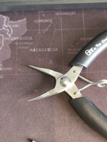
little hand-drill (affiliate link) that came with my
Hakko FR-301 Desoldering Gun kit to slowly a carefully widen the pad-holes at DL22. And this is possible because the board is only 2-sided (not multi-layered).
I had a
pack of tiny drill bits (affiliate link) ranging from 1.0 to 1.5mm in size, and I went up in size, one by one, to slowly widen the DL22 pad holes. I twister very slowly such that no copper was lifted by accident at all. Ultimately, I was able to make the holes wide enough for the larger DO-201 Zener legs to fit through.
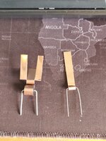
After that, I used some nippers to cut off the cap holding the Aligator Clip center bar in place, which holds the top and bottom of the copper alligator clip sides together. That wasn't too hard with hand nippers because the copper is a lot software than other metals like stainless steel. To make it easier, you can even cut up the shorter half of the clip before you cut off that center-bar-cap.

That allowed me to use the longer side of the clip which has the crimp-feet, which I used to hold the clip securely around the legs. And there is a HOLE in that side of the alligator clip which I used nearest the body of the diode. I used my hot air station set to 365°C and a soldering iron set to 350°C with a fat 4mm wide tip (larger tip sizes allow more heat to be applied) to first put a little solder around that hole to make it easier to solder to each Zener diode leg. When I did the soldering, I tried to keep the heating time as short as possible so as not to damage the diode. I used Helping Hands to hold it during my soldering, and I used a couple aluminum heatsink clips to draw as much of my soldering heat as possible away from the diode (not sure if that helped in light of the close proximaty of my solder application point to the diode body).
I also used needle-nosed pliers to bend-put the middle part where the center bar once held the clip together, and those stick out like little half-circles with holes in the middle.
The result is shown in my photos below.


You can see how much larger the DO-201 package size is compared to the 5W Zener I was using before...

It's larger in length and in width.
It fits into DL22 pads like this...


Not wanting anything to short against the nearby metal cage, I applied some rubbery epoxy to a location that won't prevent the lid of that cage from being removed...


But I later realized that epoxy was totally unnecessary because the cage is Ground, and the Anode side of the 18V Zener (which comes very close to the cage) is also Ground! So even if the Anode side Heatsink was to touch the metal cage, it wouldn't be a problem.
Before I soldered the Zener, I scraped away a good amount of the solder mask so I could apply a larger clump of solder. I covered the unused DL21 pads with the solder too. Most of the heat should flow into the two copper clip-halves I attached to the Zener's legs, but any remaining heat would then be sunk into the large amount of solder on the solder side of the board, which you can see here...

Here are more photos after it was soldered...


I replaced the nearby capacitor, because the person who had recapped that Analog Board in the past (before I received the machine) used a silly 85°C rated cap there, which is a huge no-no in that super hot area. All caps should be rated 105°C or higher! Also, the cap that was used there had the wrong Lead Spacing and was stood up on its legs with no hot glue — another huge error on the part of whoever recapped the board. So I bought a cap with the correct lead spacing which allows the cap's base to sit flush with the board.
After that install was done, I then did Voltage Testing. With my previous (physically smaller) 5W Zener, I measured 19.3V, which was higher than it should have been because the Zener is "5% tolerance" and therefore should regulate up to a maximum of 18.9V. Maybe the diode is getting too hot and that is why the actual regulation was 19.3V? Possible. But look at what I get now with the DO-201 diode (with my copper heatsinks) while the Back Side Power Switch ON and the Mac BOOTED...
18.4V! Yeah!


I then Shutdown the Mac, which increases the voltage slightly, but even then I was only getting slightly higher voltage...
18.5V! Great! Nicely below the 18.9V max voltage this 5% tolerance Zener should regulate to.

Having the expected voltage of about 18.4V~18.5V was so nice to see!
I then started taking
Thermal Measurements, noting that my ambient room temperature was
29°C, which is about the same as the room temperature of my previous thermal measurements.
5 Min. after switching on the back side Power Switch (not booted):
17 Min. after switching on the back side Power Switch (not booted):
Immediately after Booting (which drops the voltage and therefore drops the Zener temps)...
Don't forget, this is with the rear housing removed and no fan running while booted.
33 Min. after booting... (Running the Daystar Power Demo the whole time, with the LC575 motherboard’s CPU clocked at the stock 33MHz)
Soon after SHUTDOWN (voltage rises so temps rise)...
The maximum temperature I measured, which was only a minute later...
Compare that
114°C to the
133.9°C I measured with the smaller 5W Zener soon after shutdown. The larger DO-201 diode, in combination with my two hand-crafted copper heatsinks, is about
20°C cooler in terms of the maximum temperature measured soon after Shutdown.
25 Min. after Shutdown, the Zener had cooled a bit to just under 106°C. With the smaller Zener, I the temps at that point in time had dropped to only 125.2°C. So the larger Zener with heatsinks is still a very nice
19.2°C cooler at this point.
When I measured the outside part of one of the Alligator clips, toward the top, it measured 75°C, which is much cooler than the body of the Zener. Note that I used only solder to secure the clips to each diode leg. I didn't try to add any thermal glue at the part where the clip meets the body. Thermal glue may or may not draw a bit more heat from the body into each clip.
Overall, I am extremely pleased with this result and recommend it to anyone who doesn't mind a little hand-drilling to widen the pad holes at DL22. It's not hard with the right tool, and if you take it slow, it won't damage anything. You need about 1 hour to do all the work I did. And when you consider that the hottest temps are reduced by about 20°C, it's a meaningful difference. Not sure if the reduced temperatures are what led to the more accurate voltage regulation, but 18.4V is better than the 19.1V I got with the smaller and hotter Zener.
With this setup in place, I am less concerned about heat damage when the machine is accidentally left switched ON at back. Still a good idea to keep it switched OFF to save energy, but the physically larger DO-201 Zener diode with copper heat-sinks should result in longer diode life.