Color Classic VGA Woes

Marconelly

Tinkerer
May 2, 2025
36
27
18
More things happened today. First, I've replaced the 2nd optoisolator, but as I suspected, the voltages remained the same, and in general nothing changed. Then, I replaced the two 5600uF caps and one 3300uF cap with my preferred Panasonic ones. Again, no changes in voltages, but since the CC was now working fine in VGA anyway, I decided to just call it quits there and just enjoy the fruits of my repair.

And then, as I was playing around, I heard the ramping squeal of high voltage, and seconds later computer shut itself down :( I restarted it a minute later, and it again worked fine for about five minutes, then the same thing happened.

So I took the board back out, desoldered my caps and put the originals back in. Started it up again, it worked fine for some minutes, but then again the squeal and the shutdown.

Then, as I was taking the board back out again to remove the 2nd optoisolator and put back the original one, I noticed that the CRT molex cable was really stuck and couldn't be removed without some serious pulling. This didn't happen before, so I was puzzled by it. I thought that maybe the connector had some residue in it that got melted due to some arcing and caused this. With some force and lots of wiggling I managed to remove it, and then I sprayed lots of contact cleaner in there. I did also remove the 2nd optoisolator and put the original back in.

With that done, the computer worked fine for the next whole half an hour, so I called it a day there. I'll keep testing tomorrow, but I actually suspect that molex connector was the culprit for this new problem, as I can't imagine the new optoisolator would cause it - especially seeing that replacing the 1st optoisolator actually fixed the original major problem with the board. I just hope that contact cleaner on molex did really fix this long term.
 
Last edited:
  • Wow
  • Like
Reactions: JDW and jibsaramnim

Marconelly

Tinkerer
May 2, 2025
36
27
18
For a sanity check, today I've put back my preferred Panasonic capacitors back on the board. Then I've thoroughly cleaned the pins on the board where the CRT molex connector goes. Each of the four pins had some darkening on it - some residue or a burnt metal surface due to arcing? Not sure what it was but I've removed it thoroughly, and again cleaned with more contact cleaner. Assembled it all back, and had the computer running for almost two hours. Everything was perfectly stable, no weird sounds or anything. Phew! Lots of little things that can go wrong with these analog boards, other than just recapping.
 
  • Love
Reactions: jibsaramnim and JDW

Marconelly

Tinkerer
May 2, 2025
36
27
18
I just can't catch a break with this. After working perfectly for whole three days - and I used it a few hours each day - today the computer starting shutting down all on its own again, same way as it did before I thought I fixed it by cleaning the CRT connector. It seems it works fine for about five minutes, but I guess as soon as something in there gets warmed up, it shuts down.
No idea what to do now. Maybe replace those TDA4605 power delivery ICs? Replace some of those large transistors? Try to transplant the Flyback from the LC 575 board and do some adjustments to make it work like TechKnight showed in one of his videos? Or just give up and go back to my regular resolution board, where most things work fine anyway, if I use the fVGA utility :\
 
  • Sad
Reactions: JDW

JDW

Administrator
Staff member
Founder
Sep 2, 2021
1,980
1,668
113
54
Japan
youtube.com
But the computer is working. If it was a blown component, I suspect it wouldn't ever work. And so, it could be the case of something over-heating, especially now that we are into the warmer months.

What you really need is a thermal camera. Then you can leave the back case off and check temperatures inside.

I have a UTi260B, and here's how the inside of my Mac IIci look when I check its Radius Rocket card:

1750401210716.png


The downside is they are a bit expensive, even if you get the iPhone attachment kind.

I bought mine from Banggood in 2023, but I see the lowest price on AliExpress today:


Even then it's not a cheap device. Good, but not cheap. And I'm not sure how tariffs would be handled for folks based in the US.
 

Marconelly

Tinkerer
May 2, 2025
36
27
18
The things is, it's really haphazard. Today again I've been able to use it for an entire hour, and it still keeps working just fine. Yesterday it wouldn't run for longer than 5 minutes at a time.

I keep suspecting that flyback on this board is dying - it's flat surface looks pretty cracked from the heat - which maybe could explain this weird behavior, if something inside is just slightly shorted, but it manifests only sometimes.

In any case, it feels practically impossible to troubleshoot it when it can at times work for hours at a time. I would never have a real idea if replacing some component actually fixed it, unless I'd use it for days after.

*edit* Not to forget, this board still doesn't quite reach 5V/12V. It's at 4.8/11.5V right now, so maybe I should start adjusting that PP7 pot which I believe affects the low voltage? I also need to check high voltages and possibly adjust PP1 for that.
 
Last edited:

Marconelly

Tinkerer
May 2, 2025
36
27
18
Right now, I've adjusted the PP7 pot, and managed to get the low voltage to be 4.998 / 5.004 V and 11.8. Up from 4.8V / 11.5V
- I can confirm with certainty now that PP7 affects both the 5V and 12V. Not sure if it affects anything else, but those two it affects for sure.
- Turning PP7 clockwise lowers the voltage and turning it counter-clockwise increases the voltage (yes, it works in a counter intuitive way)
- PP7 is very touchy. It took me many back and forth tries to adjust it from 4.8 to 5V as I kept over/undershooting slightly even though I was moving it in very, very small increments. While you can adjust it while the computer is running, I'd suggest adjusting it only bit-bit while the computer is off, then turning computer on briefly to measure the voltage, turning it off again and re-adjusting.
- I measured voltages on the SCSI molex connector, as that's where I believe the raw analog board output can be measured, and since I'm sure the problem I'm having is solely with AB, that's what I want to measure.

@JDW there is a much older thread here where you inquired about this pot, and I hope this clears things up a bit. I am now running the computer to see if it shuts down again, but later in the day I will measure voltages on the high voltage side and maybe adjust PP1 accordingly. From what I understand with the VGA mod, the high voltage is supposed to be 68.4V rather than the original 60V, and it can be measured on the test point TP1.
 
Last edited:
  • Love
Reactions: JDW

Marconelly

Tinkerer
May 2, 2025
36
27
18
I found out where TP1 is and what it's connected to, so I can measure it from the top of the board.
I'm assuming I would measure between TP1 and say metal shielding that's connected to the ground? Would I be looking for 68.4V DC or AC here?

I want to check this because even though the computer now can seemingly run for hours, it eventually does shut down on its own. Yesterday it was running two rounds for three hours each (with a brief manual shutdown in the middle) but eventually it shut down on its own. I guess even if it stays like this, I'll take it as a win. I doubt I'd ever use the CC for more than an hour or two at a time.

*edit* So I measured 70V DC between TP1 and ground while there was a picture on the screen, and 84V for a brief period right after the bootup where there was still no picture on the screen. I guess that seems normal, so I probably shouldn't touch PP1 pot.
 
Last edited:
  • Like
Reactions: JDW

JDW

Administrator
Staff member
Founder
Sep 2, 2021
1,980
1,668
113
54
Japan
youtube.com
I found out where TP1 is and what it's connected to...
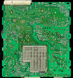
For the sake of people who later find this thread, below is crystal clarity as to where TP1 is located on the bottom of the Color Classic's ANALOG BOARD (marked with red arrow)...

CC_AnalogBoard.jpg

... I probably shouldn't touch PP1 pot.
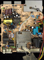
Again, for clarity I have marked PP1 with a red arrow below...

CC-AnalogBoard_TOP.jpg

(I also marked PP7 with a green arrow.)

As mentioned on PowerCC here, it's considered "risky" to adjust PP1 but perhaps "necessary" if someone has excessively thick black borders after the 640x480 mod and if first changing the value of capacitor CL26 doesn't result in the black border thickness reduction.

The cautionary text on PowerCC is as follows (slightly rewritten by me for improved readability):

The PP1 adjustment affects +60V (+84V after modding), +24V, and +8.4V. It affects the Geometry & Video adjustments pertaining to the following:
  • Horizontal drive transistor
  • Horizontal pre-drive FET
  • Pin-phase correction IC
  • Vertical drive IC
  • Video processing IC
  • RGB Gain adjustment (Green & Blue only)
Mr. Tak says that if you want to adjust PP1, please adjust carefully while measuring voltage with a meter.

I'm assuming I would measure between TP1 and say metal shielding that's connected to the ground? Would I be looking for 68.4V DC or AC here?
It is DC voltage and therefore your meter needs to be set to DC when measuring it at PP1.
And yes, you can put your meter's Black GROUND lead to the metal shield which provides a good ground.
 
  • Like
Reactions: Marconelly

Marconelly

Tinkerer
May 2, 2025
36
27
18
For the sake of people who later find this thread, below is crystal clarity as to where TP1 is located on the bottom of the Color Classic's ANALOG BOARD (marked with red arrow)...

View attachment 21930
That's where it is, yes. I have found that it leads to J23 jumper lead on the upper side, and measured between there and the metal cage, while the computer was running:

J23.jpg
 
Last edited:
  • Like
Reactions: JDW

Marconelly

Tinkerer
May 2, 2025
36
27
18
Looks like the last piece of the puzzle to get this board fully operational was to increase the picture adjustment R/G/B pots at the back of the board. I used to keep them pretty low to avoid sub-brightness being too high (I originally didn't know the VG2 pot can be used to correct this globally) and it seems like keeping these color pots very low was what contributed to the board shutting itself down after some time of running.

The reason I even readjusted these was simply that the picture brightness was too low, and I wanted to correct that. Now that I keep these pots much higher, I've been running the computer for hours on end every single day and it's been rock solid, plus the brightness is of course much better. No idea how or why those color pots affected the stability of the board, but I'm happy that it's all working now.
 
  • Like
  • Love
Reactions: eric and JDW

JDW

Administrator
Staff member
Founder
Sep 2, 2021
1,980
1,668
113
54
Japan
youtube.com
That’s great to hear! Useful information too. But what did you mean when you said “sub-brightness”?
 

Marconelly

Tinkerer
May 2, 2025
36
27
18
That’s great to hear! Useful information too. But what did you mean when you said “sub-brightness”?
Not sure if I'm using the right term, but what I mean by sub-brightness is the brightness of a pure black color. Ideally, that should be zero on a CRT, no light should be emitted for black pixels - but when I started using this board, the black color was very visibly bright and green tinted. So to compensate for that, I turned down all the color-related pots on the back, and even then it wasn't enough, which is when I eventually learned the bigger VG2 pot can be used to turn this down even further. But as I was doing all this, I did notice that at times, the picture became unstable, and I thought this was because VG2 was losing contact - so I doused it with contact cleaner. But maybe picture was randomly unstable because everything was turned down so much? Now, I've turned pots on the back up as far as it made sense, and adjusted sub-brightness using the VG2 pot. I'll keep testing it over the next few days, but so far so good!
 
  • Like
Reactions: JDW

JDW

Administrator
Staff member
Founder
Sep 2, 2021
1,980
1,668
113
54
Japan
youtube.com
...what I mean by sub-brightness is the brightness of a pure black color. Ideally, that should be zero on a CRT, no light should be emitted for black pixels
OK thanks. It's easier to ponder on B&W CRTs like the SE/30. And when you crank up the brightness on the Analog Board too high, you can actually see odd bits of light in the otherwise black border surrounding the display area. Then you know you need to back down the brightness at the Analog Board POT. So it is similar on color CRTs like the Color Classic. I now understand what you mean.