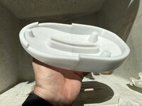
eMac swivel Base

caver01

Tinkerer
Oct 30, 2021
189
130
43
There was a time when I was seeking a decent price on an eMac base. I have come to realize that I should have just been satisfied finding a base at any price. You can get them attached to an eMac if you are lucky, or you can sometimes find folks selling just the base for about $100. Not long ago, I picked up a ”pair” of eMac swivel bases, only to realize when they arrived that I did not look at the pictures in enough detail. They were literally just the base part—one half of a swivel base. I chalked it up to my own fault for not paying enough attention.

Recently, I realized that it would not be that hard to 3D print the upper half—the part that attaches to the eMac itself. I have a complete base to work from as a reference, so I took some measurements and went to work in CAD.

Now, I am not giong to make any claims for being a great modeler. In fact, I do most of my work in TinkerCAD which I have always thought of as the Nickelodeon of CAD software. But I like it because I can usually get what I need out of addititve and subtracive primitives and I can do the work solely on my iPad. Given the fact that I used TinkerCAD, I think my eMac base part came out pretty nice!
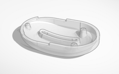
t725.png

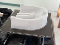
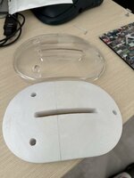
Now that I had a model, I printed a few sub-sections to ensure the holes lined up and made some final adjustments. I finally printed the whole part, but I had to cut it in half since I own a Prusa Mini+ which has a 180mmx3 build volume. While the original is molded in crystal clear acrylic, I used white PETG.
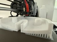
IMG_0669.jpegIMG_0667.jpegIMG_0685.jpeg

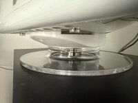
To my astonishment, it actually works! The white plastic is fine against the existing white shell of the eMac, and with a set of original hardware, it functions just a well as the real thing (the bottom section IS the real thing, of course).
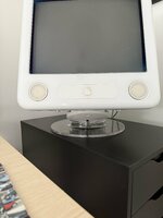
IMG_0678.jpegIMG_0677.jpeg

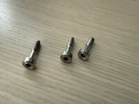
The final step is to get some appropriate hardware. I have the base screw which presents a short threaded rod from the bottom. I will need to check the thread size but I am thinking I can secure it to the base with a washer and a F-F coupling standoff. You saddle my 3D part over this standoff, then, add a short screw with a washer to cap it off. For attaching to the eMac I will need three (3) screws—maybe they are M4? They are about 17mm and probably don’t need the unthreaded section. I think I can get away with 20mm hex bolts. Here is the apple hardware that I will try to duplicate from the hardware store:
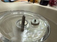
IMG_0681.jpegIMG_0682.jpeg

Does anyone have any specific details on what works here? Or maybe you want to swap an upper section and hardware for a lower section? In any case, once I figure out the screws etc. I will post my model if anyone cares.
 
Last edited:

caver01

Tinkerer
Oct 30, 2021
189
130
43
I am finally getting this accessory finished and revisiting this post to provide the final details.

First, the three socket-head screws that affix the upper base section (the part I 3D printed) to the bottom of the eMac:

These turned out to be 4mm x 16mm, .70 thread pitch. Basically, they are M4 socket head screws. I picked some up at the hardware store in stainless at USD $1.49 each. I should probably have an assortment of M4 like I do M3, M2.5 etc.

The hardware store version uses a slightly larger hex key to screw them in than Apple’s. Also the Apple screws have threads only on the tips. This is fancy as itt lets the screws turn freely in the plastic base and more or less be “captured” which is very handy, but not a deal breaker. If I really wanted to, I could chuck them into my drill and file off the threads up near the head.

For joining the lower section of the base to the upper section, I decided to step away from metric and use much cheaper US standard imperial fasteners based on a 1/4 - 20 thread. I always like this thread because it is the common size used for tripod mounts, It proved to be the perfect, inexpensive setup as flollows:

IMG_0832.jpeg


If we look at this from the bttom-up, we start on the right of this image with the bolt itself. This is a 2-inch, 1/4 - 20 bolt with a nice, solid Philips head. You run this through a fender washer, then through the large plastic bottom base, then another washer and a jam nut:

From the bottom:
1. 2-inch 1/4 -20 bolt
2. 1-inch fender washer
3. Plastic base (lower section)
4. 1-inch fender washer
5. Jam nut. Tighten this down.

The jam nut is thinner/flatter than a standard hex nut. This is important because the combined thickness with the washer cannot sit proud of the top side of the lower base section. This is because the mating base part is like a bowl that has to sit down flush over this and clear the nut (though the bolt goes up and through it).

Next, you slip on a “Steel Sleeve” which is 1/4 x 3/8 x 1. It’s one inch high and 3/8 OD which is perfect. At this point you can place the 3D printed base upper section over the post, top with a nylon washer, another 1” washer and self-locking nut. Done.

6. Steel Sleeve 1/4 x 3/8 x 1
7. Plastic base (upper section—3D print)
8. Nylon washer
9. Self-locking nut

This whole assembly now gets attached the base of the eMac (you remove one screw to be replace with the base screw in front) using the three M4 16mm screws above.

IMG_0831.jpeg


There are a few things that make this a success. First, the post you are making is fixed to the lower section with the jam nut and the steel sleeve slips over this rigid post. This is important because you don’t want the post loosely wobbling back and forth and binding up the sections. Second, the jam nut is crucial. I tried a self-locking nut but it is too tall. Even though there is a recess in the lower section, it is just barely enough to clear the upper section and not hit a jam nut. A regular nut will be too high. Finally, the sleeve provides smooth travel of the upper section—just like the original hardware does—and when you tighten down the top washers with the self-locking nut, it does not compress on the upper section. The upper section slides smoothly under the fixed top which is tigtened, rigid and des not even touch it. It is there to capture the assembled parts and for guidance.

With this done, I can report that it works great. If you need a complete base, someone will need to model the lower section. I may get around to it someday, but since I have two lower sections only, I won’t need one myself.

Or, perhaps you are missing original hardware for an apple base. In that case, the hardware described above should work fine for original plastic parts too.

The next best logical improvement would be for me to get a clear resin print of this base section. That would be almost as good as original! Maybe I will some day.

Here is a link to the model if you wish to download and try printing one yourself:
https://www.printables.com/model/1355417-emac-swivel-base-upper-sectoin
 
Last edited:

caver01

Tinkerer
Oct 30, 2021
189
130
43
Just assembled another 3D printed eMac swivel base part! In spite of my diminutive 180x180mm print bed (Prusa Mini+) this part again came out perfectly usable:

IMG_0936.jpeg

Although I'd love to see what a full part would look like printed in solid resin which would be the ideal replacement, I probably won't print another. I have a pair of swivel "bottom half" stands (incomplete--missing this part) and this will complete them. My first one has been attached and supporting a heavy eMac for months now and shows no sign of fatigue while the swivel action remains balanced and smooth. And after spending a hour or so in the fasteners section of my local hardware store, I figured out the bolt situation so that anyone who is missing hardware can refer to the post above and get a working base again.

A couple things I will mention about the printing process that may help someone reading this in the future:

1. I used white PETG filament from Creality. I get pretty good results on the Prusa Mini using this. No stringing, good bed adhesion.
2. I setup the parameters for .2mm layers, 3 perimeters (.4mm nozzle, nice and rigid) and 15% gyroid infill. This makes the part nice and strong.
3. Had to make a cut in the model at the midpoint where the edge steps down for ventilation. This is not ideal, but necessary on small printers.
4. I used 1.75mm "dowels" in the cut so it can be assembled using 10mm lengths of filament (.2mm tolerance).
5. Used snug supports across the entire curved underside. In retrospect, maybe I should have tried printing it upside-down this time.
6. Due to irregular contact with supports and some minor warping, I had to do a bit of sanding to try to make the bottom smooth. Joined with superglue and the filament dowels, I was also able to fill gaps with more CA and baking soda. This sands nice and smooth and isn't really noticeable as filler over white PETG. Sanding the seam smooth after joining seems to be the way to go.

You can actually get away with a lot here. This part is mostly invisible under the eMac. Even though this upper section mates with a circular base and follows a spherical contour, I am surprised how smoothly a bumpy, irregular (imperfect) surface still works fine as a swivel. I thought for sure it would require a glass-smooth surface on my part, but that's not the case at all. It basically sits in a "rim" atop the round base part, and only makes a ring of contact with it. This is a good design that holds strong but does not introduce much friction. Upshot: Even the worst print will probably work just fine!

One thing I did this time was added .2mm "discs" in the slicer up inside the three bolt holes. This allows the printer to bridge right over the holes with a layer, then continue to build the tops of the cone-shaped screw mounts. You can just poke through this layer with your screws later. This technique saves the hassle of using supports up inside a long tube.
 
Last edited: