

BACKGROUND
My employer has been selling off our vintage Macs on Yahoo Auctions Japan over the past several months. Prior to selling our G4 Cubes, I needed to fix their Power Bricks by way of RECAPPING. I was rather shocked to find pretty much no info on that topic online. Seems more people are trying to swap out the guts with a modern PSU, but I think it's easier to just recap. The stock brick is powerful enough for heavy upgrading. It merely needs new capacitors. You technically can resurrect a Power Brick by replacing only one particular cap inside, but I think its best to recap all the electrolytics.OPENING
Getting the Power Brick open is a hassle. I was eager to get mine open so I didn't photograph or video the entire process, but you can see one of the major disassembly guides here:Just note that even if you drill holes like that fellow suggests, you still won't get those plastic end caps off without breaking one of the plastic tabs inside that hold it on. Trust me, I was meticulous and spend a huge amount of time trying, but the plastics are brittle and hard. Ultimately one of the tabs will break.
Here's a video that basically shows what the above iFixit link shows, plus the video shows how to remove the black plastic & copper plates, which you must carefully and meticulously remove before you gain access to the PCB solder side (to remove the stock caps):
But as I said, when removing the end caps, one of the two tabs broke on both of the end caps. What I did was use DCM to fix the broken tabs. It's not glue. It melts the plastic slightly in order to weld plastic parts together. The big caveat is that DCM is toxic stuff that requires care when handling, but I first used it to fix my Macintosh Portable plastics, so I know it works. I had some DCM left over from that, which you can read about here. Just note that superglue isn't strong enough to hold the tabs in place when you put the end caps back on. BONDIC isn't strong enough either.
Here are my tabs after I reattached them using DCM...
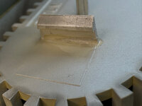
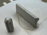
Also note that after you get all the plastics off and reveal the metal innards, you need to get the metal cage apart. The iFixit guide I linked for you above is only semi helpful. There are 3 metal tabs on each side which hold the cage together, and I could only get one of the three out on either side. I ended up having to take some durable metal cutters to cut off the remaining two metal tabs. It will still go back together (if you don't bend the cage too badly), and the outer plastic will hold the two cage parts together fine. You might be able to get it apart without cutting any of the tabs though, so be sure to try.
REMOVING the Black Plastic & Copper Plates
When following the above YouTube video to get the black plastic plates off, you will see you need to desolder some points. The first point is actually the GROUND side of one of the capacitors you will be replacing, and the stock soldering looks like this up close...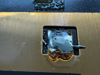
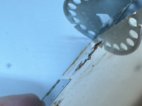
I used my Hakko FR301 desoldering gun with ease to remove that solder, but a copper braid would work just as well. You will need a lot of heat though -- 400°C at least.
Then you will need to remove the other shield which has two points that need desoldering...
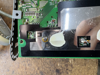
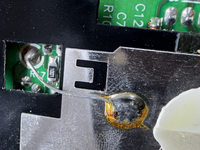
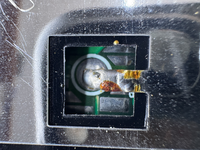
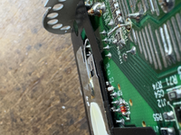
It may be a bit challenging because the thin white blobs you see in the above photos are silicone which is used to lightly glue the pieces together. It doesn't take to much effort to break that silicone, but it will take more effort than you think. Just don't tear off any of the solder points you see in the above photos when pulling those black plastic plates apart. But follow the video I linked for you above because it shows that you must remove two screws on the copper side, and you must also remove black tape on the opposite side too.
STOCK CAPACITORS

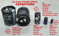
SILKSCREEN MARKINGS
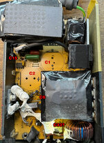
I couldn't tell if the lower marking was C33 because most of the silk on my PCB was gone. Might be something else. Hence the "?" that I added to all references on this page which refer to C33.
NOTE: There was a little black metal piece that was affixed to the top of the white 5W power resistor, show at left of C33 in the photo above. I had to remove it to get C33 out. I scraped off the old white silicone from the white resistor and from the black metal piece, then swapped the capacitor at C33, then used this silicone to put it back in place, at the point when I was done and doing the reassembly:
I couldn't get the white version, but other than color, the transparent version I bought is the same silicone. However, I do see the white version on Amazon USA here (affiliate link):
I cannot be 100% sure that was what Apple used, but my extensive discussions with AI led me to the brand and model of silicone I ultimately purchased. It is silicone for general use in power supplies and securing PCB components, NOT the kind of silicone that also provides good thermal transfer. I tested the stock white silicone and confirmed the thermal transfer was low, proving the stock white stuff isn't transferring heat effectively. Again, that white stock silicone is there to hold parts in place well over long periods of time while enduring the heat of the power supply.
REPLACEMENT CAPACITORS
These are what I purchased from Mouser in August 2026 (see my Mouser Cart below):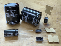
Physical size for C1, C2 and C33 matched the stock caps. The new C6 was a tad bit smaller, and my replacement for C15 was a tad bit bigger.
(NOTE: I did NOTE end up using that 25V rated 47uF capacitor.)
 IMPORTANT!
DO NOT cut the NEGATIVE (–) lead short on capacitor C33? because it needs to be like the stock cap. You will solder that long negative lead to the PCB and also to one of the black & copper plates. Note how long the negative lead is on the stock C33? cap: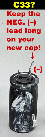
LCR METER MEASUREMENTS (ESR, etc.)
I measured the stock and replacement caps with my DE-5000 LCR meter so you can see how they compare...G4 Cube Power Brick
Stock Capacitors
@120Hz
- 700uF (C1): -87.2°, Q=21.1, D=0.046, ESR=80mΩ
- 699uF (C2): -87.2°, Q=20.5, D=0.048, ESR=90mΩ
- 855uF (C33?): -87.6°, Q=25.2, D=0.039, ESR=60mΩ
- 194uF (C6): -84.9°, Q=11.45 , D=0.087, ESR=590mΩ
- 43.9uF (C15): -86.9°, Q=19.11 , D=0.052, ESR=1.59Ω
@1kHz
- 682uF (C1): -73.3°, Q=3.34, D=0.299, ESR=60mΩ
- 680uF (C2): -73.1°, Q=3.31, D=0.301, ESR=71mΩ
- 824uF (C33?): -80.6°, Q=6.08, D=0.164, ESR=31mΩ
- 173uF (C6): -78.1°, Q=4.77 , D=0.209, ESR=191mΩ
- 41.76uF (C15): -79.2°, Q=5.25 , D=0.190, ESR=721mΩ
=========================================
Replacement Capacitors
@120Hz
- 708uF (C1): -87.4°, Q=22.5, D=0.044, ESR=80mΩ
- 708uF (C2): -87.4°, Q=23.0, D=0.043, ESR=80mΩ
- 972uF (C33?): -88.0°, Q=30.6, D=0.032, ESR=40mΩ
- 210uF (C6): -88.0°, Q=30.1, D=0.033, ESR=21mΩ
25V part (I did NOT use this)
- 48.4uF (C15): -88.2°, Q=33.7, D=0.029, ESR=810mΩ
50V part
- 45uF (C15): -88.8°, Q=50.1, D=0.020, ESR=560mΩ
@1kHz
- 692uF (C1): -74.0°, Q=3.5, D=0.285, ESR=65mΩ
- 693uF (C2): -74.0°, Q=3.51, D=0.284, ESR=65mΩ
- 940uF (C33?): -82.4°, Q=7.56, D=0.130, ESR=21mΩ
- 200uF (C6): -84.8°, Q=11.2, D=0.089, ESR=70mΩ
25V part (I did NOT use this)
- 46.4uF (C15): -85.6°, Q=13.29, D=0.075, ESR=258mΩ
50V part
- 43.7uF (C15): -87.2°, Q=20.6, D=0.048, ESR=176mΩ
I bought both a 25V and 50V for C15 to see which is better and ultimately went with the 50V, which has superior specs in every way and will physically fit just fine.
Just to let you know, C15 tends to be the one that fails. So using a robust replacement will bode well, I think.
The second cap that can sometimes fail is C6.
The two big ones are probably OK, but they are old, so why not replace them too? That way, you won't need to worry about any of those caps for another 25+ years.
MOUSER CART
These are the replacement caps I used (the best picks I could find):https://www.mouser.com/en/Tools/Project/Share?AccessID=e231f829c7
TESTING
You should measure the No Load voltage coming out of your newly recapped Power Brick before connecting it to your Cube. I would suggest you do that before you clamp down the metal cage, although you should test voltage only after you solder down the black plastic (and copper) plates that cover the PCB solder side. Be sure you can measure 28V according to the diagram below.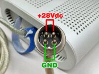
Good luck!