Logic Board - Macintosh SE Reloaded

JDW

Administrator
Staff member
Founder
Sep 2, 2021
1,581
1,378
113
53
Japan
youtube.com
@JdM74 , I will read and respond to PMs tomorrow because it's but a long and tiring day. But before I go to bed, I just want to say...

SE Schematics (Apple and Bomarc) are downloadable here:

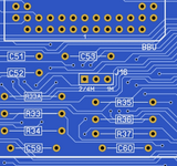
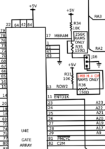
The section showing J16 (RAM size selection jumper) is this:

1715865343771.png
 

JdM74

Tinkerer
Jan 16, 2024
36
36
18
49
Georgetown TX
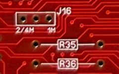
Finally got to testing things out. My initial tests were just focused on the jumpers, which appeared to have continuity as expected.
In a conversation with @JDW, I got a little more direction and did some further testing. The results were:

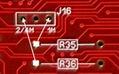
When testing, I did it in either direction, using the red probe on the resistor and then the black--
• Touching either probe to the left side of R35 and on the 1M pin, got a beep
• Touching either probe to the left side of R36 and on the 2/4M pin, got a beep
• As expected, the center pin did nothing.

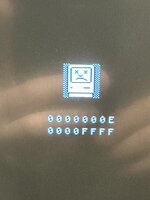
@callanbrown You indicate that your system crashed upon startup. Was this a bomb when software started to load or a Sad Mac? If it was a Sad Mac, what was the error code thrown? That definitely would be useful to try and help isolate the possible problem.
 

Attachments

  • 00 JDW's Reference Board.png
    00 JDW's Reference Board.png
    198.5 KB · Views: 38
  • 01 My Board - No Annotations.png
    01 My Board - No Annotations.png
    47.1 KB · Views: 37
  • 02 Beep Tests.png
    02 Beep Tests.png
    48.7 KB · Views: 37
  • Love
Reactions: JDW

callanbrown

New Tinkerer
May 10, 2022
22
2
3
Finally got to testing things out. My initial tests were just focused on the jumpers, which appeared to have continuity as expected.
In a conversation with @JDW, I got a little more direction and did some further testing. The results were:

When testing, I did it in either direction, using the red probe on the resistor and then the black--
• Touching either probe to the left side of R35 and on the 1M pin, got a beep
• Touching either probe to the left side of R36 and on the 2/4M pin, got a beep
• As expected, the center pin did nothing.

@callanbrown You indicate that your system crashed upon startup. Was this a bomb when software started to load or a Sad Mac? If it was a Sad Mac, what was the error code thrown? That definitely would be useful to try and help isolate the possible problem.

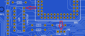
You say the center pin did nothing - this is the problem I had, it should be grounded, not "nothing". there is a center plane in the PCB sandwich that the center pin should be connected to.

So you should continuity check the center pin to a ground pin. See if the two points with arrows gives you a beep.

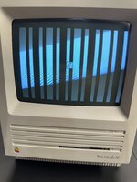
Before I fixed this problem on my board, I'm pretty sure I was getting vertical lines sometimes on bootup, other times I believe I could get to the desktop before it would freeze. I don't think I got error codes or sad macs.
 

Attachments

  • pins.png
    pins.png
    37.3 KB · Views: 41

JdM74

Tinkerer
Jan 16, 2024
36
36
18
49
Georgetown TX
Hiya @callanbrown. Alrighty...after some further looking into things, here's what I found:

1. When using a 1MB setup [4x256KB SIMMs]...placed in SIMM1 and SIMM2, with J16 set to the 1MB position - startup chime with vertical lines.
2. When using a 2MB setup [2x1MB] placed in SIMM1 and SIMM2, with J16 set to 2/4M - no startup chime, immediate Sad Mac.
3. When using a 2MB setup [2x1MB] placed in SIMM3 and SIMM4, with J16 set to 2/4M - no startup chime, random screeching from speaker and random lines on the display.
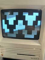
4. When using a 2.5MB setup [2x1MB + 2x256KB] with the 1MB SIMMs in SIMM1 and SIMM2 and the 256KB SIMMs in SIMM3 and SIMM4, with J16 set to 2/4M - startup chime and what appears to be a large smiley face.
5. A 4MB setup with 4x1MB - startup chime, no other issues.

I tested the points you indicated in your last post, Pin 8 of U2F and the center pin of J16, no beep.

@Kai Robinson...for your review.
 

Attachments

  • 01 - 1MB Setup.jpg
    01 - 1MB Setup.jpg
    750 KB · Views: 33
  • 02 - 2MB Setup.jpg
    02 - 2MB Setup.jpg
    594.9 KB · Views: 31
  • 03 - 2.5MB Setup.jpg
    03 - 2.5MB Setup.jpg
    611.7 KB · Views: 31

callanbrown

New Tinkerer
May 10, 2022
22
2
3
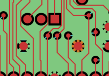
I'm looking at the Gerbers and connection to the ground plane is indeed missing. Kai, I DM'd you on Discord about this back in September and you said it was there in Sprint, so maybe the Gerber export screwed up?

In the attachment you can see the three big pins (one is square). The middle should be connected to the ground plane. In the bottom right you can see what a pad connected to a plane looks like.
 

Attachments

  • missing_gnd.png
    missing_gnd.png
    20.9 KB · Views: 36

JdM74

Tinkerer
Jan 16, 2024
36
36
18
49
Georgetown TX
Heya @Kai Robinson More detail for your review.

I got my SE put back together after the little ADB fiasco I found myself in. First startup, there was some happiness....a startup chime, followed by an arrow pointer and a disk with a flashing question mark. OK, I thought...we're gonna be good. Then the testing began. Here are those findings:

Floppy related:

• Inserting a floppy disk into the internal floppy drive, connected to the Lower internal connector - the disk immediately was ejected with a flashing ❌.
• Shut down, changed to the Upper internal connector. Same thing happened -- the disk immediately was ejected with a flashing ❌.
• Shut down again, connected a known good external floppy drive -- another go of the disk immediately being ejected with a flashing ❌.
• Shut down, disconnected the external floppy drive and used a FloppyEMU...the disk remained mounted on the FloppyEMU, disk with flashing ❌
• Shut down, disconnected the FloppyEMU from the external port and connected to the Lower internal connector, same result.
• Shut down, disconnected the FloppyEMU from the Lower internal connector and connected to the Upper internal connector, same result.

The IWM was known to be good before the build began.

The internal floppy drive is connected using a red-striped ribbon cable, the same one that came from the donor machine. I even tried with a yellow-striped cable from a Mac Plus [also known to be good]. As noted above, same results. The floppy drive being used has been recapped, cleaned, lubricated and tested rigorously before reinstallation into the rebuilt SE.

SCSI related:

• When connecting an external hard disk or BlueSCSI to the external connector, there is no activity.
• When connecting a SCSI hard disk or internal BlueSCSI to the internal port, the system boots normally.

The SCSI chip used was an NCR 53C80-40, which in past reading was not known to be an issue. At least on the SCSI bus, there are signs of life.

I used a Hard Disk 20SC for the external drive with System 6.0.8, a known good Apple Quantum 40 from another SE with a known good System 6.0.5 installation. The BlueSCSI card has System 6.0.8.

ADB related:

Using a 'modern replacement' PIC chip...with a keyboard and mouse connected -- the mouse pointer is jumpy and sometimes 'clicks' itself without the button being pressed. The keyboard is responsive at times, others not. Disconnecting and reconnecting the ADB cable will make things work for a moment, then stop again. I did discover that the Bourns filter at U11B was installed backwards [Pin 1 at Pin 10...my bad there]. I fixed that, but the same phenomena still remains.

If there is a list of things to test/check, let me know and I will make it so and report back.
 

Kai Robinson

TinkerDifferent Board President 2023
Staff member
Founder
Sep 2, 2021
1,165
1
1,173
113
42
Worthing, UK
Hello chaps! It does indeed look like the Gerber export didn't include that, for whatever reason - here's what i'm seeing in Sprint:

Screenshot 2024-05-22 232139.jpg


Circled is the middle pin, which is very much connected to the ground plane - luckily, as you pointed out, this is an easy fix - solder a bodge wire to the right hand side of C53, that's the nearest ground plane point. C51 or C52's right hand side will also work.

I'll do a clean export of the sprint original along with the gerbers, put them on GitHub shortly and send this over to Mark @ MacEffects - Revision 1.6b is going to be the CURRENT version, as i've spotted a naming issue with the additional address line tap-point i added for the SMC to do a Classic ROM adapter.

Thank you to everyone for bringing this to my attention - I hate it when issues like this crop up!
 

Kai Robinson

TinkerDifferent Board President 2023
Staff member
Founder
Sep 2, 2021
1,165
1
1,173
113
42
Worthing, UK
@JDW Might be better placed to help, as his earlier revision board, once built, was booted successfully - James, did you test the floppy functionality? I can't see anything wrong with the IWM/SWIM routing

@JdM74 did you get the board made yourself, or from MacEffects?
 

JdM74

Tinkerer
Jan 16, 2024
36
36
18
49
Georgetown TX
@JDW Might be better placed to help, as his earlier revision board, once built, was booted successfully - James, did you test the floppy functionality? I can't see anything wrong with the IWM/SWIM routing

@JdM74 did you get the board made yourself, or from MacEffects?

@Kai Robinson The 1.5b board was purchased direct from MacEffects. .
 
Last edited:
  • Like
Reactions: Kai Robinson

JdM74

Tinkerer
Jan 16, 2024
36
36
18
49
Georgetown TX
I've been meaning to publish an update here to things that happened back in late May.

Since then, the issues with the first SE build [v1.5b] have been resolved. Those issues were centered around Floppy, SCSI and ADB.

Interestingly enough, all of the issues were fixed by changing out the CayMac Vintage Bourns recreations for original ones [located at U8B and U11B]. The other two CayMac Vintage Bourns remained soldered to the board. I also took that opportunity to socket those two chips. Once I did that, things sprang to life.

Lesson here - check your Bourns! They are important. =)

There were changes made to the board, related to a memory jumper issue [v1.6b]. I ended up purchasing boards to do a couple of more builds. Build #2 on the 1.6b board went MUCH better than the first. Of course, there were a lot of lessons learned from the first build. While it was suggested that some chips not be socketed, I socketed everything, except for the ADB filter at U11A. I thought about it, but that would have sat kind of high on the board and I didn't want to run into any issues with that.

Build #3 is up and coming. Spent quite a bit of time extracting chips from the donor board. Since I didn't source other NOS parts from places, this build will be almost 100% from donor parts...except for those things that are readily available from Mouser or DigiKey and parts already purchased for the purposes of this final build.
 

Willj

Tinkerer
Apr 28, 2022
62
38
18
I am the same person that runs CayMac Vintage and here is a great problem solving story for you all related to posts in this thread.

I recently received the SE Reloaded board for @fred1212 discusses in this thread and privately shared that info with JDW for feedback. A few other people who had tried to repair the board were unsuccessful. JDW suggested that sharing details of my repair would likely help other people avoid the same mistakes in their own SE Reloaded builds. I have written all the details below. The links to my live videos related to this board are here:


PROBLEMS: When I received the board, it would not boot. I eventually got it to boot, but then there was a strange 10 second delay with a checkerboard screen before the bong finally sounded. Then it would boot, but it crashed when doing Snooper 2.0 CPU & Accelerator tests.

REPAIRS:

1. BBU had a broken pin/leg so it was not usable. Good thing I had a few donor boards.
2. The builder mistakenly soldered in R32 & R33, but they are not needed. I removed them.
3. A broken trace was found in SIMM sockets 1 & 3. I repaired it.
4. A broken trace was found for the BR signal on the CPU to its resistor. I repaired it.
5. Two resistors were the wrong values. I swapped them out for the correct values.
6. The 0.1uF caps that were used all over the board were not the recommended axial type, so I changed them all to axial. While doing this, I found that many of the blue caps used for the 0.1uF were cracked and the legs loose on the cap itself. I guess this happens when you take legs and stretch them that much to use as axials. I also replaced the others caps that were not axial of different values that I took from a donor board.
7. I tried a complete new set of chips on the board and still had the same problems. This tells me that what I have done so far and the chips is not the solution. (Well, one chip was found to have issues, which I will mention below).
8. I contacted JDW to ask for his thoughts. I also watched JDW’s SE Reloaded videos again and checked over all resistors over the entire board. Used JDW’s BOM as a guide along with the videos so I could check all the values. All were good.
9. Checked both sides of the motherboard again for broken traces and none were found. The board was booting at this point, thanks to the fixes mentioned above, but the board still had a 10-second delayed chime and checkerboard screen before it would finally boot. That problem could no longer be blamed on bad traces or any of the chips I swapped out.
10. I ultrasonic cleaned the board again and let it dry out.
11. When booting into System 6.0.8, I ran snooper but it kept getting locked-up (crashing) at the end of the CPU tests.
12. I changed main crystal but made no change.
13. I decided to check the normal axial 33uF 16v capacitors on the board and HERE IS WHERE THINGS GET STRANGE!!!!
14. The markings on the caps was VERY hard to read on these Vishay caps, but I noticed ALL of them were 33uF 16v; yet C36 should be a 1uF 50v cap.
15. I tested all the Vishay caps with a meter and noticed that they were ALL saying 50uF or more and not 33uF.
16. I removed all the Vishay caps and re-tested with a proper tester, and all were showing to be 50uF or more.
17. The 1uF 50v was not there! Instead, I found it was a 33uF marked capacitor, but it also was measuring to be 50uF. This cap is on pin 7 of the sound chip, and this is how the sound chip monitors the power rail to be sure it is ready to start up and take reset high. With this cap being WAY over value, it was taking longer to charge it up to reach the level needed for the chip to say “OK I am here and can wake up now.”
18. I had a few cap kits from Console5 for the SE, so I cleaned up the holes and put in the new caps.
19. Plugged all in and turned it on and VIOLA, instant chime!!!! No more delay. So this solved the main issue but still had another issue.
20. With it booting now, I booted into 6.0.8 and ran Snooper 2.0, but the CPU test at accelerator test would still lock-up the machine.
21. It was then discovered that the CPU used was not 68000 but instead a 68010.
22. Also found out that System 6.0.8 and Snooper 2.0 do not play nice together, so I booted into 7.5.5 and ran Snooper but the CPU test continued failing.
23. Replaced the CPU with a real 68000 because TechStep was also saying there was a CPU mismatch, and I did not notice it until one of my viewers on my live stream said the lock-ups related to using a 68010 CPU.
24. With a 68000 CPU and 7.5.5 and Snooper running, the CPU test and all other tests passed! Seems the 68010 is damaged or has some issues with it.
25. TechStep passes all tests and the machine is ROCK SOLID with all items working well. REPAIR FINISHED!

@fred1212 also send me a damaged SE30 to be reloaded and a Iici to repair but the issues where internal on this board so a reloaded transfer was also done for the Iici. Both of these boards work 100% now so this is a 3 for 3 for the owner. One thing, make sure your Iici PSU is in great condition when using nubus cards.
 
Last edited:

fred1212

Tinkerer
Jul 27, 2022
130
25
28
Thanks To Will at CayMac my reloaded SE now is working but its been some journey. A great read for anyone contemplating tackling a reloaded board with limited experience, as the saying goes "not for the faint hearted"
 

Willj

Tinkerer
Apr 28, 2022
62
38
18
Had me worried that it was a bad batch of PCB's there!!
Think this was more bogus capacitors as the markings on them were white (Vishay is normally black) and all were 50uF - 55uF. It is a v1.5 board so I did do the fix for the center memory jumper pin. No other issues with it now and its working solid. Enjoyed the diagnoses work on it and surely is a nice board to work on. I will have to do some of these reloaded myself soon.
 
  • Like
Reactions: JDW

Kai Robinson

TinkerDifferent Board President 2023
Staff member
Founder
Sep 2, 2021
1,165
1
1,173
113
42
Worthing, UK
The 1.6 revision fixes a few things, silkscreen errors and provides additional address lines for a potential macintosh classic ROM swap.
 
  • Like
Reactions: JDW