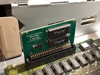
Yeah that would work. ") That will help prevent the connector pins from being bent at least in one direction.
That will help prevent the connector pins from being bent at least in one direction.
That will help prevent the connector pins from being bent at least in one direction. That will help prevent the connector pins from being bent at least in one direction.Agreed that using the cheaper standard 2.54mm pitch headers makes more sense to keep costs low.
Think cutting would be easier. I just use wire snips so it's pretty fast. If you wanted a nice clean cut then could probably make a jig with a miter saw.
I hate to disappoint, but I am not the legend behind "Garrett's Workshop"... we just share the same name with the same spelling!Nice to see you join the forum Garrett
It was always "Garrett" says something.
This kind of ruins the mysterious man behind the scenes / larger than life image I had of you though
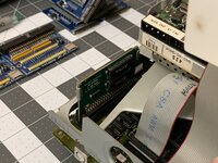
Nope, it takes regular 30-pin SIMMsGreat job!
Maybe a stupid question….
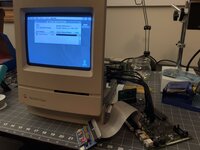
Would this also work in the Classic II ?