Yeah that would work.  That will help prevent the connector pins from being bent at least in one direction.
Low-cost 3 MB RAM card for Macintosh Classic
- Thread starter Zane Kaminski
- Start date
You are using an out of date browser. It may not display this or other websites correctly.
You should upgrade or use an alternative browser.
You should upgrade or use an alternative browser.
Hmm well the required dimensions are actually somewhat more dramatic...

It's 8.58 mm (2.7 inches) at the bottom, same as the width of the original. Looks kinda crazy though. Am I worrying about it too much? Should I just go ahead with these dimensions?
Edit: Garrett says it looks like a rocketship and if only it was a more unique and interesting gizmo we could call it the Rocket RAM and have a space theme hahahah
Last edited:
Well the aesthetics is a personal thing. I find it looks kinda interesting with the wings on the bottom. Sorta looks like a fat rocket to me lol.
I'm kinda boring/classic for design and would probably just make it rectangular with the same width as the original card from top to bottom.
I'm kinda boring/classic for design and would probably just make it rectangular with the same width as the original card from top to bottom.
Alright I'm gonna order the boards!! Then I can circle back to the WiFi card and the SE accelerator.
My $0.02 - the OEM expansion card was much taller and heavier than what you've designed, and likely needed the rails on the chassis for support due to the torque that could have potentially been exerted on the motherboard connector. With your design I wouldn't be concerned with utilization of the rails. Doing so won't hurt anything, so I suppose you can't go wrong. I am also noticing that the OEM card doesn't fit right in the center of the plastic motherboard connector. Not sure if this is by design, but it doesn't appear to be adding any structural support, only a guide to help the installer find the pins. Your latest rectangular design sure is sleek looking though!

Agreed that using the cheaper standard 2.54mm pitch headers makes more sense to keep costs low.
Think cutting would be easier. I just use wire snips so it's pretty fast. If you wanted a nice clean cut then could probably make a jig with a miter saw.
Dremel on a stand with a "diamond" cutting wheel might work well too. I cut paired 30-pin SIMM sockets that way.
Just ordered a few boards! Yeah, the wider design was the right way all along, that way it'll go in the chassis rails as well as guide the insertion of the card into the motherboard. Obvious in retrospect but the card is so short that I thought it wouldn't rise up to the chassis rails at all until I actually measured.
@Garrett I'm having the boards sent directly to you from JLCPCB and I'll send you the rest of the parts once I receive them.
@Garrett I'm having the boards sent directly to you from JLCPCB and I'll send you the rest of the parts once I receive them.
Nice to see you join the forum Garrett 
It was always "Garrett" says something.
This kind of ruins the mysterious man behind the scenes / larger than life image I had of you though
It was always "Garrett" says something.
This kind of ruins the mysterious man behind the scenes / larger than life image I had of you though
I hate to disappoint, but I am not the legend behind "Garrett's Workshop"... we just share the same name with the same spelling!Nice to see you join the forum Garrett
It was always "Garrett" says something.
This kind of ruins the mysterious man behind the scenes / larger than life image I had of you though
Update on the project:
@Garrett has assembled the board but unfortunately there is an error in the schematic.
The specific issue is that the /WE and /RAS signals have been switched on the main connector, plus the /CAS signals were jumbled up too. Oops... Okay well new boards are on the way. I will also be updating the original post soon too, archiving the old stuff and putting the new board photos and schematic on the first page.
Last edited:
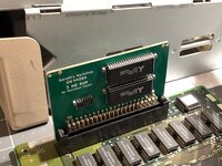
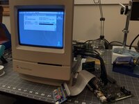
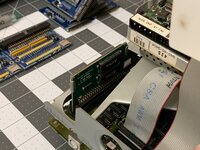
Exciting updates this evening! @Zane Kaminski's revised board design is up and running well. System boots and operates normally. The card also fits perfectly in the chassis.
If anyone has any specific tests or benchmarks they'd like to see performed, I'm happy to run them.
If anyone has any specific tests or benchmarks they'd like to see performed, I'm happy to run them.
Attachments
Good to hear! Soon I will make a batch of 50 or so. Just gotta find the RAM chips... somehow I misplaced em...
Finally we have gotten through our very long production and prototyping backlog enough to made a batch of 50 of these!

They’re going in the oven right now. Then of course we need to inspect, do any rework (shorts, etc.), hand solder on the connector, quick test, rework+test again if necessary, ultrasonic cleaning, final test, then package. So it’ll be a little bit before they’re on sale but we’re getting there.
edit:

And when the boards are in the oven, the flux boiling makes the uhh, sweet smell of successful soldering.
They’re going in the oven right now. Then of course we need to inspect, do any rework (shorts, etc.), hand solder on the connector, quick test, rework+test again if necessary, ultrasonic cleaning, final test, then package. So it’ll be a little bit before they’re on sale but we’re getting there.
edit:
And when the boards are in the oven, the flux boiling makes the uhh, sweet smell of successful soldering.
Last edited:
Great job!
Maybe a stupid question….
Would this also work in the Classic II ?
Maybe a stupid question….
Would this also work in the Classic II ?
Nope, it takes regular 30-pin SIMMsGreat job!
Maybe a stupid question….
Would this also work in the Classic II ?


